
Comment contrôler les tolérances dans les profils formés en rouleaux
Table des matières
Introduction

Producing a metal profile that looks correct is not the same as producing one that consistently meets its drawing. Width, height, flange position, bend angle, hole location, straightness, twist, cut length, and other dimensions may all affect whether a roll formed component fits correctly into a larger assembly.
Controlling roll forming tolerance therefore requires more than making final adjustments at the last roller stand. Dimensional accuracy is influenced by the complete manufacturing process, including incoming material, strip width, leveling, entry alignment, tooling design, roll gaps, shaft condition, punching, springback, straightening, cutting, and measurement methods.
The most effective approach is to define which dimensions are functionally important before production begins and then control the processes that influence those dimensions. Attempting to hold every feature to an unnecessarily restrictive tolerance can make tooling and setup more complicated without improving the actual function of the component.
For manufacturers producing long structural and industrial profiles, tolerance control should therefore begin with the finished drawing and continue throughout the complete roll forming line.
Qu’est-ce que la tolérance au roll
Roll forming tolerance defines the acceptable dimensional variation between the manufactured profile and its specified design.
A drawing may identify requirements for:
- largeur hors tout,
- hauteur hors tout,
- largeur de la bride,
- largeur de la bande,
- angle de courbure,
- bend radius,
- position du trou,
- slot spacing,
- rectitude,
- camber,
- twist,
- et longueur finie.
These dimensions do not all behave in the same way during roll forming.
Some dimensions are established directly by roller geometry. Others are influenced strongly by material springback. Hole positions may depend on servo feeding and subsequent forming. Straightness may depend on residual stress and final correction. Finished length may be determined by the measuring and cutting system rather than the forming rolls themselves.
For this reason, roll forming tolerance should be considered as a collection of different dimensional controls rather than one universal accuracy value for the entire component.
Pourquoi la tolérance doit être définie à partir de l'application terminée
A useful tolerance begins with understanding how the component will be used.
Consider a structural channel that must fit between two mating components. Its overall width may be more important than a non-functional surface dimension.
A mounting profile may depend heavily on hole position because fasteners need to align with another component.
A decorative trim profile may place greater emphasis on visible surface geometry.
A steel formwork component may require repeatable edge and connection features so multiple panels fit together during assembly.
These examples show why specifying extremely tight tolerance on every dimension does not necessarily produce a better component.
Instead, drawings should identify:
Dimensions critiques
Features that directly affect assembly, function, or interface with other components.
Secondary dimensions
Features that need reasonable consistency but do not require the same degree of control.
Reference dimensions
Measurements provided mainly for design understanding rather than direct manufacturing acceptance.
The roll forming process can then be designed around the dimensions that actually matter.
Pourquoi les tolérances de formation de rouleaux ne sont pas identiques pour chaque profil
Two profiles produced on similar machines can have very different tolerance behavior.
A simple symmetrical channel contains fewer geometric variables than a deep asymmetric profile with several bends, return lips, punched features, and changing material thickness.
The number and location of bends influence how deformation accumulates.
Material strength affects springback.
Long flanges can respond differently from short flanges.
Asymmetrical profiles may develop uneven longitudinal strain.
Punching close to a bend can influence both hole shape and surrounding geometry.
Industry specialists such as Dahlstrom Roll Form note that achievable roll forming tolerance depends on factors including tooling, number of passes, number of bends, material characteristics, profile geometry, and where dimensions are measured.
This means tolerance should be evaluated for the actual part rather than copied from a generic machine specification.
Commencez par un dessin en coupe entièrement défini
Tolerance control becomes difficult when the finished profile drawing is incomplete.
Before tooling design begins, the drawing should clearly identify:
- matériel,
- nominal thickness,
- dimensions du profil,
- angles de courbure,
- bend radii,
- punched features,
- critical dimensions,
- datum or reference points,
- longueur finie,
- and applicable dimensional requirements.
It is also important to avoid conflicting dimensions.
If several dimensions describe the same geometry from different reference points, small variations can make it mathematically impossible for every value to remain at its nominal dimension simultaneously.
The drawing should therefore establish a logical dimensional hierarchy.
Roll-Kraft’s roll form design guidance similarly begins with the finished cross-section, material information, machine requirements, and specified tolerances before the flower pattern and tooling are developed.
Choisissez la donnée de mesure correcte
One of the most overlooked parts of tolerance control is deciding where measurements begin.
Suppose a channel profile has a web and two flanges.
Should flange width be measured:
- from the outside of the bend?
- from the tangent point?
- from the inside corner?
- from the profile centerline?
Different methods can produce different results even on the same physical component.
A repeatable inspection process therefore requires clearly defined datums.
The production drawing, tooling design, and quality-control method should use compatible reference points.
This becomes especially important for complex profiles containing multiple bends.
If engineering measures from one surface while production measures from another, apparent dimensional disagreements can occur even when the actual part has not changed.
L'épaisseur du matériau est une source majeure de variation dimensionnelle
Roll forming tooling contacts the material according to an expected thickness range.
When thickness changes, the relationship between upper and lower tooling also changes.
Even when every coil is within the allowed material specification, normal thickness variation can influence:
- roll contact,
- bend radius,
- finished angle,
- profile width,
- profile height,
- and springback.
This is why extremely restrictive profile tolerances can become difficult when incoming material itself has a relatively broad thickness range.
Tooling design should therefore consider the actual material specification rather than only the nominal thickness shown in a basic drawing.
Incoming-material inspection can help identify whether a dimensional change originates from the roll forming machine or from a different coil condition.
La force de rendement et le retour élastique affectent la précision de la courbure
After metal passes through a forming roll, it naturally attempts to recover part of the imposed deformation.
This elastic recovery is known as springback.
Material with different mechanical properties may therefore leave the same roll tooling at slightly different final angles.
The effect can become visible in:
- angle de bride,
- géométrie d'angle,
- overall profile width,
- and final section height.
Tooling can compensate for expected springback through controlled over-forming and calibration.
However, compensation should be based on the actual material range.
If production changes from one steel grade to another without reviewing forming behavior, previously stable dimensions may shift.
This is one reason material grade and mechanical properties should be communicated before roll tooling is designed.
La largeur de la bande influence toute la section transversale
Strip width is another critical input variable.
The flat strip ultimately provides all of the material required to create the finished cross-section.
If strip width changes, one or more finished flange or web dimensions can also change.
For symmetrical profiles, the variation may appear on both sides.
For asymmetrical sections, it may become concentrated in one particular flange depending on how the tooling references and guides the material.
Correct strip-width calculation is therefore an important part of tooling design.
The slitting process should also maintain consistent strip width and edge quality during production.
When a profile suddenly develops dimensional variation, checking the raw strip width can prevent unnecessary roll adjustments.
L'alignement d'entrée établit la position de départ
The strip needs to enter the first forming pass at the correct lateral position.
Entry guides establish this reference.
If the strip enters off-center, the tooling may begin forming one side differently from the other.
The final result can include:
- unequal flange dimensions,
- torsion du profil,
- camber,
- shifted bend positions,
- or unstable geometry.
Roll-Kraft specifically identifies proper entry-guide setup as important for maintaining consistent profile geometry and repeatable results.
Their entry guide technical guidance explains that incorrect entry alignment can contribute to twist, camber, burr-related issues, and dimensional problems.
This is why the first step in troubleshooting a changing flange dimension should not automatically be adjusting the final roll stand.
The strip should first be confirmed at its original reference position.
La conception de l'outillage détermine l'évolution de la précision dimensionnelle
Tooling defines how the cross-section evolves from one stand to the next.
Each pass should control a specific portion of the total deformation.
If too many bends are forced simultaneously, the material can move unpredictably.
If the bend progression is poorly balanced, longitudinal stresses may alter straightness and overall geometry.
A well-designed flower pattern allows critical dimensions to develop progressively while retaining sufficient control over bend positions and material movement.
The number of forming stands therefore affects tolerance potential.
More forming passes can allow deformation to be divided into smaller stages when the profile requires it, although simply adding unnecessary stands does not guarantee better accuracy.
The correct number depends on profile complexity, material, thickness, bend geometry, and finished requirements.
L'écart de roulis doit correspondre à la conception du matériau et de l'
Roll gap affects how the tooling contacts and guides the strip.
If a roll stand is excessively tight, it can place unnecessary pressure on the material and alter its deformation path.
If the gap is too loose, the tooling may not control the profile sufficiently.
Incorrect gaps can contribute to:
- dérive dimensionnelle,
- twist,
- arc,
- marques de surface,
- inconsistent bend angles,
- and poor repeatability.
Roll gaps should therefore be established systematically rather than adjusted randomly until the final profile appears acceptable.
When multiple stands are adjusted without recording the changes, the process becomes difficult to reproduce during the next setup.
A documented baseline gives operators a known starting condition for each profile.
L'état de l'arbre peut affecter les profils de tolérance serrés
The tooling is only as stable as the shafts and bearings supporting it.
A worn or bent shaft can allow tooling movement during operation.
Even small mechanical movement can change the effective roll position as material passes through the machine.
This becomes particularly relevant when the finished component requires tight dimensional control or when thin material is being formed.
Roll-Kraft’s shaft inspection guidance notes that shaft wear, runout, and bearing conditions can translate into tooling movement and ultimately create quality problems.
Maintenance teams should therefore include shaft and bearing condition in dimensional troubleshooting rather than treating all tolerance problems as tooling-design issues.
L'usure de l'outillage provoque une dérive dimensionnelle progressive
A new roll set and a roll set after extended service do not necessarily create identical forming conditions.
Material continually contacts the tooling surfaces during production.
Over time, wear can alter:
- effective roll diameter,
- contact points,
- bend location,
- écart de roulis,
- et état de surface.
The dimensional change may be very gradual.
Operators may compensate by repeatedly adjusting the machine until the original setup values are no longer meaningful.
A better approach is to record finished-part dimensions over time.
If a critical dimension moves consistently in one direction across several production periods, tooling wear should be investigated.
Trend information can reveal problems earlier than waiting for the profile to exceed the acceptance limit.
Comment le poinçonnage affecte la tolérance au formage de rouleaux
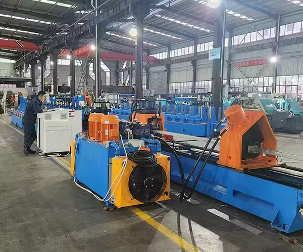
Many roll formed profiles include holes, slots, notches, or embossments.
These features create another layer of dimensional control.
A hole punched into flat strip can change its position relative to the finished cross-section after the material is bent.
The effect is especially important when the feature is close to a bend line.
Material around the hole may also deform during forming.
For this reason, manufacturers should distinguish between:
Punching-position accuracy before forming
et
Final hole position on the completed profile.
The second value is normally more important for actual assembly.
JBLDIE solutions de machines de formage can integrate feeding, punching, forming, cutting, and automated processing around the finished profile, making coordination between these stages important when hole position and profile dimensions must be controlled together.
Contrôle de l'alimentation servo Position de la caractéristique longitudinale
When hole patterns or cut lengths depend on programmed material movement, servo feeding becomes part of the tolerance chain.
The control system may command an exact feed distance, but actual strip movement can still be affected by:
- roller,
- surface matérielle,
- accélération,
- upstream coil tension,
- pression d'alimentation,
- mechanical condition,
- et synchronisation.
A displayed programmed value should therefore not be treated as proof of final dimensional accuracy.
Finished parts should be measured.
When a hole-spacing problem occurs, the troubleshooting process should determine whether the source is:
- the production program,
- actual feed movement,
- outillage de poinçonnage,
- material deformation,
- or downstream forming.
This avoids adjusting the wrong section of the line.
Le pré-poinçonnage ou le post-poinçonnage peuvent affecter le contrôle dimensionnel
The location of punched features relative to bends influences whether punching should occur before or after forming.
Pre-punching flat strip can simplify die access and integrate well with continuous production.
However, holes positioned very close to forming zones can distort as the surrounding material bends.
Post-punching can avoid some of this deformation but requires the tooling to access an already formed three-dimensional profile.
Samco Machinery notes that hole position relative to bends is an important consideration when deciding whether features should be pre-punched or post-punched.
The decision should therefore be made from the finished profile and tolerance requirements rather than from equipment preference alone.
La méthode de coupe affecte la longueur finie et la géométrie finale
Roll formed profiles may be cut before forming or after forming.
Each method creates different tolerance considerations.
Formage Pré-Coupe
Individual blanks enter the forming machine.
This removes the need to cut the finished three-dimensional section, but the free ends of the part can respond differently during forming and may be more susceptible to end flare.
Formage post-coupure
The strip remains continuous through the roll forming section and is cut after the profile has been created.
This supports continuous forming, but finished length depends on the measuring and cut-off system.
The cutting operation can also release residual stress.
As a result, profile ends may show slightly different geometry from the middle of the component.
Tolerance specifications should account for how and where critical dimensions are measured along the part.
L'éruption de fin ne doit pas être confondue avec la variation générale du profil
A profile may meet its dimensional requirements through most of its length but change shape close to the cut ends.
This phenomenon is commonly called end flare.
Residual stresses built during forming are partially released when the continuous section is cut.
The ends can then open, close, twist, or change angle.
If an inspection team measures only near the end of the part, it may conclude that the entire profile is outside tolerance even though the central section remains stable.
Drawings and quality procedures should therefore define whether specific geometric requirements apply:
- across the full length,
- through a central measurement zone,
- or with a defined end allowance.
The correct approach depends on the function of the component.
La rectitude est un autre type de tolérance
Cross-sectional dimensions and longitudinal straightness should be controlled separately.
A profile may have perfect flange and web dimensions while still showing:
- arc,
- camber,
- or twist.
These characteristics are influenced strongly by residual stress, material condition, forming symmetry, alignment, and straightening.
Attempting to correct severe upstream forming problems only with the final straightener can create an unstable process.
Ideally, the profile should leave the forming rolls relatively stable before final correction is applied.
The straightener should refine the result rather than force a heavily distorted section into shape.
Facteurs de tolérance courants au formage de rouleaux
| Facteur | Dimension or Quality Affected | Control Method |
|---|---|---|
| Épaisseur du matériau | Width, height, angle, roll gap | Incoming material verification |
| Force d'élasticité | Bend angle and springback | Material control and tooling compensation |
| Largeur de bande | Flange and overall dimensions | Slitting control |
| Entry alignment | Flange balance, camber, twist | Guide setup |
| Motif fleur | Overall geometry and residual stress | Conception d'outillage |
| Écart de rouleau | Bend control and dimensions | Standardized setup |
| Tooling wear | Gradual dimensional drift | Inspection and maintenance |
| Shaft/bearing condition | Roll position and repeatability | Mechanical inspection |
| Servo-alimentation | Hole pitch and cut positioning | Feed verification |
| Perforation | Hole geometry and position | Process coordination |
| Coupe | Longueur et état de fin | Measurement and cut-off control |
| Redressage | Arc, cambrure et torsion | Controlled final correction |
| Measurement method | Reported inspection result | Defined datums and procedures |
Pourquoi la méthode de mesure compte autant que la machine
Two inspectors can measure the same profile differently if the measurement procedure is not clearly defined.
For example, a flexible flange can move slightly when compressed by a measuring tool.
A deep channel measured across the outer edges may produce a different result depending on where the caliper contacts the part.
Bend angles can also vary depending on the length of the reference surfaces used.
The inspection method should therefore define:
- measuring instrument,
- datum,
- measurement location,
- part orientation,
- distance from the cut end,
- and whether the profile is restrained during measurement.
Repeatable measurement is essential before process capability can be evaluated.
Otherwise, apparent production variation may partly come from inconsistent inspection.
L'inspection de première pièce établit la référence de production
Before continuous production begins, a first-piece inspection should confirm that the machine setup produces the intended profile.
The first acceptable sample becomes an important reference.
Measurements can include:
- cross-sectional dimensions,
- angles de courbure,
- positions des trous,
- rectitude,
- longueur finie,
- et autres caractéristiques critiques.
If adjustments are required, they should be made systematically.
Once the profile meets the drawing, important setup values can be recorded.
This helps future changeovers because operators are not starting from an unknown condition every time the tooling is installed.
Roll-Kraft’s setup procedures similarly recommend checking the profile against the section drawing after the tooling has been adjusted and making corrections at designated control passes rather than changing every stand indiscriminately.
L'inspection en cours de processus empêche de grandes séries de variations
First-piece approval is not enough for a long production run.
Material changes, tooling wear, machine temperature, vibration, coil condition, and operator adjustments can cause dimensions to change over time.
Critical features should therefore be checked at appropriate intervals during production.
The purpose is not to measure every possible dimension continuously.
Instead, identify a smaller number of control dimensions that provide useful information about process stability.
Par exemple:
- one flange width,
- overall section width,
- one critical bend angle,
- pas de trou,
- and finished length
may be sufficient to detect whether the process is beginning to drift.
If a control dimension moves toward its allowable limit, operators can investigate before the profile becomes unacceptable.
Ne réglez pas plusieurs supports de rouleau à la fois
Random adjustment is one of the fastest ways to lose process repeatability.
If a dimension changes, operators sometimes tighten or loosen several roller stands until the final profile appears correct.
The immediate result may improve, but the cause becomes unknown.
A better approach is to understand which forming pass controls each major dimension.
When a particular feature drifts, the relevant control stand can be inspected first.
Only one meaningful variable should be changed at a time whenever practical.
The result should then be measured and recorded.
This creates a cause-and-effect relationship that can be repeated during future production.
Les tendances statistiques sont plus utiles que les mesures uniques
One part slightly closer to nominal does not necessarily mean the process has improved.
Tolerance control becomes more reliable when production data is viewed as a trend.
Suppose flange width remains within the allowed range but gradually changes across multiple inspection samples.
That trend may indicate:
- usure d'outillage,
- variation matérielle,
- guide movement,
- machine heating,
- or another changing process condition.
Waiting until the dimension crosses the acceptance limit loses the opportunity for early correction.
Factories do not necessarily need complicated analytics to benefit from trend monitoring.
Even a basic dimensional log can show whether a process remains centered or is slowly drifting.
Évitez d'utiliser le redressement final pour masquer les problèmes de formage
Straighteners are useful for controlling longitudinal profile condition.
However, excessive straightener adjustment can mask an upstream problem.
If the section leaves the forming stands with significant bow or twist, forcing it straight afterward may create high internal stress.
The result may change again after cutting or handling.
When a straightener requires increasingly aggressive adjustment, operators should check:
- incoming material,
- entry alignment,
- écarts de roulis,
- tooling progression,
- alignement du stand,
- and shaft condition.
A stable roll forming process should create a profile that requires only controlled final correction.
Changeover Procedures Are Important for Repeatable Tolerance
A machine that produces multiple profiles needs to return to known setup conditions each time tooling is changed.
Repeatable changeover requires more than storing PLC settings.
Mechanical references should also be controlled.
Ceux-ci peuvent inclure
- tooling position,
- entretoises,
- écart de roulis,
- emplacement du guide,
- position de roulement latéral,
- réglages du redresseur,
- outils de poinçonnage,
- and cutting configuration.
Tooling components should be clearly identified.
Setup records can help operators reproduce successful conditions instead of rebuilding the process from memory.
The more frequently a line changes products, the more valuable standardized changeover becomes.
How to Troubleshoot a Roll Forming Tolerance Problem
A dimensional problem should be traced from upstream to downstream.
Start by confirming the drawing and measurement method.
Make sure the part is actually being measured from the correct datum.
Next, inspect incoming material.
Check thickness, width, straightness, material specification, and edge condition.
Then confirm entry alignment.
Follow the strip through the forming stands and identify where the dimension first begins to move away from the intended progression.
Inspect relevant tooling, roll gaps, shafts, bearings, and guides.
If the issue involves holes or length, evaluate servo feeding, punching, measuring, and cutting.
Finally, confirm straightening and finished-part condition.
This sequence is much more reliable than automatically adjusting the final roll stand.
A Practical Tolerance-Control Workflow
A robust process can be organized into five stages.
1. Define
Identify critical dimensions and functional interfaces on the finished drawing.
2. Design
Develop the tooling, forming progression, punching sequence, and cutting strategy around those requirements.
3. Establish
Create baseline machine settings using verified material and approved first-piece samples.
4. Monitor
Measure selected control dimensions during production and record meaningful trends.
5. Correct
When variation appears, identify the source systematically and change one relevant process variable at a time.
This creates a closed-loop approach to dimensional control.
Tolerance is no longer something inspected only after manufacturing. It becomes part of the production process itself.
When Tighter Tolerance Requires a Different Production Strategy
Sometimes a requested tolerance cannot be achieved reliably by simply adjusting an existing machine.
The requirement may influence the entire manufacturing strategy.
Tighter control can require:
- more controlled raw material,
- additional forming passes,
- different tooling,
- improved machine stiffness,
- more precise shaft and bearing systems,
- post-forming calibration,
- different punching sequence,
- different cutting method,
- or more frequent inspection.
This is why tolerance requirements should be communicated before the production line and tooling are finalized.
A machine selected around a basic profile shape may not automatically meet every future precision requirement simply through control-system changes.
The profile drawing and tolerance expectations should be part of the original equipment discussion.
How to Evaluate Tolerance During Machine Acceptance
When a new roll forming line is tested, inspection should focus on finished products rather than only whether the machine operates.
Representative material should be used where possible.
Le test doit confirmer:
- dimensions du profil,
- angles de courbure,
- rectitude,
- position du trou,
- longueur coupée,
- état de surface,
- and repeatability across multiple consecutive parts.
If the line is designed for several profile sizes, representative changeovers should also be evaluated.
A single correct sample does not demonstrate stable process control.
The important question is whether the machine can repeatedly produce the specified profile under the agreed production conditions.
Conclusion
Roll forming tolerance is the result of an entire manufacturing system rather than one machine adjustment.
Incoming material thickness and strength influence springback. Strip width affects the available material across the section. Entry guides establish the starting position. Tooling and roll gaps control progressive deformation. Shafts and bearings determine how consistently the tooling remains positioned. Punching, servo feeding, cutting, and straightening add their own dimensional variables.
Effective tolerance control begins by identifying which dimensions actually matter to the finished component.
From there, the tooling and production process can be developed around clearly defined datums and realistic requirements. First-piece inspection establishes a baseline, while in-process measurement and trend monitoring help identify dimensional drift before it becomes a larger production problem.
For manufacturers developing new metal profiles, dimensional requirements should therefore be discussed at the same time as material, tooling, punching, cutting, and automation. Designing the line around the finished component provides a stronger foundation for repeatable profile accuracy than attempting to correct tolerance problems after production has already begun.
FAQ
What is roll forming tolerance?
Roll forming tolerance is the acceptable amount of dimensional variation between a manufactured roll formed profile and its specified drawing. It can apply to width, height, bend angle, hole position, straightness, twist, length, and other features.
What affects roll forming tolerance the most?
Tolerance is influenced by several connected factors, including material thickness, mechanical properties, strip width, tooling design, roll gaps, machine alignment, shaft and bearing condition, punching, cutting, and measurement methods.
Can tighter roll forming tolerances always be achieved by adjusting the rollers?
No. Some tolerance requirements may require changes to material control, tooling design, number of forming passes, machine construction, punching sequence, cutting strategy, or inspection method. Roller adjustment alone cannot correct every source of variation.
Why do roll formed dimensions change between different coils?
Different coils may vary in thickness, yield behavior, residual stress, width, or other material characteristics. These changes can influence springback and the way the strip interacts with the tooling.
How can manufacturers maintain consistent roll forming tolerances?
Start with clearly defined drawings and measurement datums, control incoming material, establish repeatable machine settings, inspect critical dimensions during production, maintain tooling and mechanical components, and troubleshoot dimensional changes systematically.
Need to Improve Profile Dimensional Control?
Roll forming accuracy depends on the relationship between the finished drawing, material, tooling, feeding, punching, forming, cutting, and inspection method. If you are evaluating a production line for profiles with specific dimensional requirements, contactez JBLDIE to discuss your drawings, material specifications, tolerances, and processing requirements.
 French
  English
  Arabic
  Russian
  Spanish