
How to Reduce Tube Mill Changeover Time Between Sizes
Table of Contents
Introduction
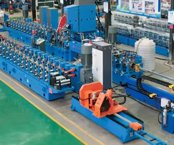
A tube mill may run efficiently for hours once production is stable, but the situation changes when the factory needs to switch from one tube diameter, wall thickness, or profile size to another. Roll tooling needs to be changed or adjusted, fin passes need to be reset, the weld section may require a different setup, sizing rolls need to match the new tube, and the first finished pieces still need to be verified before full production resumes.
This makes tube mill changeover one of the most important hidden factors affecting actual tube production capacity.
The fastest changeover is not simply the one where operators replace the rolls quickly. A more useful definition is the time from the last acceptable tube of Product A to the first acceptable tube of Product B. This is also consistent with the quick-changeover approach described by the U.S. National Institute of Standards and Technology, which defines setup reduction around the interval between the last good piece of the current run and the first good piece of the next run. NIST’s Lean and Process Improvement guidance provides a useful broader manufacturing reference for this approach.
For manufacturers producing many round, square, and rectangular tube specifications, reducing changeover time can therefore improve effective production without increasing maximum line speed.
What Is Tube Mill Changeover?
Tube mill changeover is the complete process required to move a tube production line from one product specification to another.
A product change can involve:
- tube diameter,
- square or rectangular dimensions,
- wall thickness,
- material grade,
- strip width,
- welding setup,
- finished length,
- or several of these variables at once.
Depending on the mill configuration, operators may need to change or adjust:
- entry guides,
- breakdown rolls,
- side rolls,
- fin-pass rolls,
- weld rolls,
- induction coil,
- impeder,
- squeeze-roll setup,
- scarfing tools,
- sizing rolls,
- straightening equipment,
- cut-off settings,
- and control recipes.
For manufacturers evaluating an integrated system, JBLDIE’s Tube Mill Production Line covers continuous processes including strip forming, welding, sizing, cutting, and related production operations for round, square, and rectangular tubes.
The more product specifications a factory needs to manufacture, the more important a repeatable changeover strategy becomes.
Why Changeover Time Matters More Than Maximum Mill Speed
Machine specifications often emphasize maximum production speed.
For example, two tube mills may both be capable of operating at a similar meters-per-minute rate under appropriate production conditions.
But Factory A runs one tube size for several days.
Factory B changes specifications several times in one shift.
Even if both mills have the same nominal running speed, their effective daily output can be very different.
Actual available production time includes:
running time + changeover time + maintenance + quality adjustment + other stops
If changeovers consume a large portion of every shift, increasing maximum line speed may provide only limited improvement.
This is why factories with mixed production should pay attention to:
qualified tubes per shift
rather than only:
maximum meters per minute.
The Real Definition of a Fast Changeover
A common mistake is to stop the stopwatch as soon as the new tooling is installed.
That does not represent the real production interruption.
A more realistic tube mill changeover sequence is:
- The last qualified Product A leaves the line.
- Production stops.
- Existing tooling is removed or adjusted.
- New tooling is installed.
- Mechanical settings are established.
- Welding equipment is adjusted.
- Strip is threaded.
- Trial tube is produced.
- Dimensions and weld conditions are checked.
- Corrections are completed.
- The first qualified Product B is approved.
The useful metric is therefore:
Last good tube A → First good tube B
This logic is closely related to SMED, or Single-Minute Exchange of Die, a lean-manufacturing method focused on reducing manufacturing changeover and setup losses. A useful overview is available from Wikipedia’s SMED reference.
The objective is not to assume every tube mill should literally change size in a few minutes. The value of the approach is in identifying which tasks actually require downtime and which can be prepared before the mill stops.
What Usually Takes the Most Time During Changeover?
Changeover time can be divided into several different areas.
| Changeover Stage | Typical Work | Common Cause of Delay |
|---|---|---|
| Production stop | Clear current product | Poor scheduling |
| Tool preparation | Locate new rolls and spacers | Poor organization |
| Tool removal | Remove existing tooling | Slow fastening |
| Tool installation | Install new roll set | Incorrect order or identification |
| Stand setup | Set roll gap and height | No recorded baseline |
| Entry setup | Center strip | Guide wear or misalignment |
| Fin-pass setup | Prepare weld geometry | Trial-and-error |
| Weld setup | Position welding components | Poor reference positions |
| Sizing | Establish final dimensions | No setup records |
| Threading | Feed strip through the mill | Poor preparation |
| Trial production | Produce initial tubes | Setup errors |
| Inspection | Verify new tube | Unclear acceptance method |
| Correction | Adjust process | Too many variables changed together |
The largest improvement opportunity is often not asking operators to work faster.
It is removing unnecessary:
- searching,
- waiting,
- guessing,
- repeated adjustment,
- and rework.
Mill Condition Comes Before Quick-Change Hardware
Quick-change technology provides limited value if the mill itself cannot return to a repeatable mechanical condition.
Problems such as:
- worn shafts,
- loose bearings,
- damaged keyways,
- adjustment backlash,
- misaligned stands,
- worn guides,
- or unstable metal-line height
can make each changeover behave differently.
An operator may install the correct tooling but still spend a long time adjusting the new tube because the machine does not return to its previous mechanical reference.
This leads to an important rule:
Do not try to solve poor mill condition only with faster tooling replacement.
Maintenance and setup reduction need to work together.
Shaft and Bearing Condition Affect Repeatability
Roll tooling references the machine shafts.
If a shaft moves, deflects, or runs incorrectly, the roll position changes with it.
Before trying to reduce changeover aggressively, inspect:
- shaft condition,
- runout,
- keyways,
- bearing condition,
- bearing blocks,
- shaft shoulders,
- stand alignment,
- and mechanical looseness.
Baseline settings create value only when the machine can physically return to the same condition during the next production campaign.
A recorded roll gap is much less useful if shaft or bearing movement changes the real loaded gap during operation.
Entry Guides Need a Repeatable Reference
The entry section establishes the strip position before forming begins.
If the strip enters the breakdown section off-center, that error can influence the entire tube mill.
Possible consequences include:
- unequal edge positions,
- unstable forming,
- seam movement,
- weld V variation,
- and inconsistent finished dimensions.
During changeover, operators should therefore verify:
- guide condition,
- guide-roll position,
- centerline,
- metal-line height,
- and relationship with the first forming pass.
A worn or loose entry guide can turn every new product setup into extended troubleshooting.
Prepare Tooling Before the Mill Stops
One of the simplest ways to reduce tube mill changeover time is to complete as much preparation as possible before the current production run ends.
Before Product A finishes, the team can prepare:
- next roll set,
- spacers,
- side rolls,
- fin rolls,
- weld rolls,
- setup gauges,
- fasteners,
- required tools,
- lubrication,
- setup chart,
- and product recipe.
This follows one of the fundamental ideas behind quick changeover: move tasks that do not require the machine to be stopped outside the downtime window.
Instead of:
stop machine → find tooling → inspect tooling → prepare tools → begin changeover
the process becomes:
prepare everything → stop machine → perform necessary changeover work
The mill should stop because the active tooling needs to be changed, not because operators still need to search for equipment.
Tool Identification Prevents Setup Errors
Tube mill roll sets may contain many individual components.
Without clear identification, operators can:
- install a roll in the wrong stand,
- reverse its orientation,
- use the wrong spacer,
- mix components from different tube sizes,
- or lose time confirming which roll belongs where.
A structured tooling-management system can identify:
- tube size,
- stand number,
- upper or lower position,
- left or right orientation,
- spacer arrangement,
- and storage position.
This reduces dependence on operator memory and makes changeover more repeatable across different shifts.
Use Setup Charts Instead of Memory
Experienced operators remain extremely valuable, but the production system should not depend entirely on what one operator remembers.
A setup chart can store successful mechanical settings for each product.
Useful information may include:
- entry-guide position,
- roll gaps,
- side-roll positions,
- fin-pass settings,
- welding-section references,
- squeeze-roll settings,
- induction-coil location,
- impeder position,
- sizing-roll settings,
- straightener settings,
- and initial production speed.
When the same tube size returns, the production team can begin close to a previously qualified condition instead of recreating the setup from zero.
Record Mechanical Settings Alongside PLC Recipes
Modern tube mills may store digital product recipes containing:
- line speed,
- cut length,
- drive values,
- welding references,
- alarm settings,
- and production quantities.
However, many important setup variables remain physical.
Examples include:
- guide location,
- roll position,
- spacer arrangement,
- weld-roll position,
- side-roll height,
- induction-coil location,
- and impeder position.
A stored PLC program cannot compensate for incorrectly installed tooling.
The strongest changeover system combines:
digital recipe + mechanical setup record + standardized procedure
rather than relying on only one of them.
Preset Tooling Before Threading
Where equipment design permits, important tooling gaps and positions can be established before material enters the machine.
This can include:
- breakdown-roll clearance,
- side-roll location,
- fin-pass position,
- and welding-section reference positions.
The first strip then enters a mill already close to its intended setup.
This reduces the amount of adjustment required after threading.
It also makes it easier to distinguish between a genuine material/process problem and a basic installation problem.
Breakdown Section Setup
The breakdown section begins transforming flat strip toward the tubular shape.
Poor setup here can later appear as a welding problem.
During changeover, verify:
- the correct roll set,
- roll orientation,
- spacers,
- gaps,
- stand alignment,
- and strip centerline.
The strip should enter the breakdown section consistently.
Do not depend on downstream fin passes or guides to compensate for a major upstream positioning error.
The earlier the material path becomes correct, the easier the rest of the setup becomes.
Side-Roll Adjustment
Side rolls help control the developing tube between major forming passes.
Depending on the machine design, they may require adjustment in:
- horizontal position,
- vertical position,
- roll spacing,
- and metal-line height.
If adjustment mechanisms contain significant backlash or wear, operators can spend considerable time repeatedly correcting the setup.
Quick-release or indexed adjustment systems can reduce manual changeover work, but only when they return the tooling to a repeatable position.
Fast movement without accurate positioning does not shorten good-part-to-good-part changeover.
Fin-Pass Setup Is Critical for Welding
The fin section prepares the strip edges before the welding point.
After changing size, fin passes need to establish stable:
- tube circumference,
- strip-edge location,
- weld V geometry,
- and entry into the welding section.
If these mechanical conditions are wrong, operators may begin changing:
- welding power,
- squeeze pressure,
- coil position,
- or impeder position
in an attempt to compensate.
This can extend changeover significantly.
The better approach is to stabilize the pre-weld tube geometry first.
Welding Setup Should Use Repeatable References
The welding section needs to match the new tube diameter, wall thickness, and forming condition.
Instead of rebuilding the setup entirely through visual judgment, factories can establish reference values for recurring products.
These can include:
- weld-roll position,
- squeeze-roll position,
- induction-coil location,
- impeder location,
- and scarfing setup.
Where practical, components for the next product can also be prepared offline before production stops.
This converts more work into external preparation and reduces actual mill downtime.
Induction Coil and Impeder Preparation
In a high-frequency welded tube mill, changing tube size can also require a different induction coil or impeder configuration.
Before the current run ends, verify that the correct components are:
- available,
- clean,
- undamaged,
- correctly identified,
- and ready for installation.
A damaged or incorrectly positioned impeder can make welding appear unstable even when the roll tooling is correct.
Operators may then waste time adjusting electrical parameters to compensate for a physical setup problem.
Preparing welding-system components in advance reduces this risk.
Squeeze-Roll Setup
Squeeze rolls bring the heated strip edges together and contribute to weld consolidation.
After a tube size change, verify:
- correct roll size,
- alignment,
- pressure,
- seam position,
- and mechanical condition.
Too little effective pressure can affect joint formation.
Excessive pressure can increase weld upset and distort tube geometry.
Previously verified settings provide a much better starting point than rebuilding the process from visual judgment during every changeover.
Sizing Rolls Establish Final Dimensions
After welding and cooling, sizing rolls bring the tube toward its required finished geometry.
For round tubes, this primarily involves diameter control.
For square and rectangular tubes, the downstream process can include additional reshaping and calibration.
Operators should establish:
- correct tooling,
- roll position,
- centerline,
- gap,
- and final dimensional references.
If the factory produces square and rectangular sections, the related Square Tube Forming Machine page provides an additional JBLDIE internal reference for equipment used in square, rectangular, and related tube/profile processing.
Final sizing should refine a stable tube rather than attempt to repair major errors originating in breakdown forming or welding.
Round-to-Square Lines Require More Changeover Work
Some tube mills first produce a welded round tube and then reshape it into a square or rectangular section.
Changing products can therefore require both:
upstream tube mill changeover
and
downstream square/rectangular sizing changeover.
Additional settings may include:
- square-forming rolls,
- corner geometry,
- width,
- height,
- diagonals,
- and straightening.
Factories producing a combination of round, square, and rectangular tube should include these tasks when calculating practical changeover time.
Direct Square Forming Has a Different Changeover Strategy
Direct square forming systems may use adjustable or shared tooling concepts to reduce some physical roll changes across a defined size range.
This can be useful for factories producing many square and rectangular sizes.
However, fewer roll replacements do not mean zero changeover.
Operators may still need to adjust:
- guides,
- forming positions,
- welding equipment,
- sizing,
- straightening,
- cutting,
- and control recipes.
The same performance measure remains relevant:
last qualified old product → first qualified new product.
Rafted Tooling Can Reduce Downtime
One approach to faster changeover is mounting complete forming sections on removable rafts or cassettes.
Instead of changing individual rolls while the mill is stopped, another tooling set can be prepared offline.
While Product A runs:
- Product B tooling can be installed on another raft,
- inspected,
- adjusted,
- and prepared.
During changeover, the factory exchanges the complete assembly.
This can substantially reduce internal setup work for high-mix production.
However, raft systems also require:
- additional floor space,
- transfer or lifting systems,
- accurate docking,
- tooling storage,
- and additional investment.
They are most useful when frequent product changes justify the system.
When Quick-Change Equipment Makes Sense
Quick-change technology becomes more attractive when:
- changeovers occur frequently,
- production batches are short,
- tube sizes repeat regularly,
- lost mill time is significant,
- and tooling can be prepared offline.
A factory producing the same tube for several weeks at a time may obtain less benefit.
A factory changing several times per shift can obtain much greater value.
The production schedule should therefore influence the changeover strategy.
Standardize the Changeover Sequence
Different operators should not need completely different methods for changing the same tube size.
A standardized sequence might include:
- Controlled production shutdown.
- Tooling removal.
- Machine and tooling inspection.
- New tooling installation.
- Pregapping.
- Entry alignment.
- Fin-pass setup.
- Welding-system setup.
- Sizing setup.
- Threading.
- Trial production.
- Inspection.
- Final correction.
- Release to continuous production.
The exact procedure depends on the machine.
The value comes from making successful setup repeatable.
Changeover Safety Must Be Built Into the Procedure
Tube mill changeover involves direct interaction with tooling, shafts, rolls, drives, hydraulic systems, electrical systems, and other potentially hazardous equipment.
Where servicing or tooling changes expose personnel to unexpected energization or stored energy, the applicable energy-control procedure needs to be followed.
The U.S. Occupational Safety and Health Administration’s Control of Hazardous Energy (Lockout/Tagout) standard covers servicing and maintenance involving potential unexpected startup or release of hazardous energy and specifically addresses activities such as adjustment and tool changes under covered conditions.
Actual requirements should follow the machine, workplace, jurisdiction, and applicable safety regulations.
Changeover improvement should never depend on operators bypassing required isolation or safeguarding procedures simply to save time.
Separate Internal and External Tasks
One of the most useful quick-changeover concepts is separating tasks according to whether the machine genuinely needs to be stopped.
Internal Tasks
These can only be performed during the shutdown period.
Examples can include:
- removing active tooling,
- installing replacement tooling,
- threading material,
- and final machine setup.
External Tasks
These can be completed before the machine stops.
Examples include:
- locating rolls,
- cleaning replacement tooling,
- checking component condition,
- preparing gauges,
- preparing inspection instruments,
- loading product data,
- and organizing fasteners.
The goal is to move as much work as practical out of the internal downtime window.
Tube Mill Changeover Improvement Table
| Problem | Typical Cause | Improvement Direction |
|---|---|---|
| Tooling takes too long to find | Poor storage | Tool identification |
| Setup varies by shift | Operator-dependent process | Standard procedure |
| Long adjustment after tooling change | No baseline values | Setup charts |
| Welding takes too long to stabilize | Mechanical pre-weld setup incorrect | Repeatable references |
| Same size never repeats | Mechanical wear | Maintenance and alignment |
| Operators wait during shutdown | Sequential preparation | Move tasks outside downtime |
| Many trial tubes required | Setup based on guessing | Preset and measure |
| Reported changeover seems fast but production is not | Wrong timing definition | Good-part-to-good-part timing |
| Wrong rolls installed | Poor labeling | Tool identification |
| PLC recipe is correct but tube is wrong | Mechanical setup mismatch | Mechanical + digital recipe |
First-Piece Inspection Should Be Prepared in Advance
Once the new size begins running, the quality team should know exactly what needs to be measured.
Depending on the finished tube, checks may include:
- outside diameter,
- square width,
- rectangular height,
- wall thickness,
- seam position,
- weld condition,
- corner geometry,
- straightness,
- cut length,
- and surface condition.
The instruments and inspection method should be prepared before changeover begins.
Otherwise, the production line can remain idle after setup simply because the team is still preparing to measure the first product.
Quality preparation is part of changeover preparation.
One Good Tube Is Not Enough
A single acceptable tube does not prove that the new setup is stable.
Several consecutive products should be checked according to the factory’s inspection requirements.
The purpose is to distinguish:
one temporarily acceptable piece
from
a repeatable qualified process.
If dimensions drift during the first several tubes, additional process stabilization may still be required.
Reduce Startup Scrap as Well as Time
Changeover performance is not measured only in minutes.
Poor setup can also generate substantial trial material before the new specification becomes stable.
Startup losses may include tubes with:
- incorrect dimensions,
- unstable welds,
- poor scarfing,
- sizing errors,
- wrong cut length,
- or surface defects.
The real impact of changeover therefore includes:
downtime + startup scrap + labor + quality verification.
A slightly longer mechanical setup that produces qualified tube quickly may be better than an extremely fast roll change followed by a long period of scrap production.
Track Changeover KPIs
Factories can record several useful indicators.
| KPI | What It Shows |
|---|---|
| Good-to-good changeover time | Real production interruption |
| Tool replacement time | Mechanical change efficiency |
| Setup adjustment time | Repeatability of baseline settings |
| Trial-material length | Startup scrap |
| First-pass acceptance | Setup quality |
| Number of adjustments | Process stability |
| Changeover by product pair | Difficult size transitions |
| Changeover by team | Training or procedure variation |
This data can reveal whether the next improvement should focus on:
- tooling,
- maintenance,
- operator training,
- preparation,
- automation,
- or production scheduling.
Product Pair Matters
Not every size transition requires the same amount of work.
A change from one nearby round diameter to another may be simpler than changing from:
small round tube → large rectangular tube
depending on the mill design.
Factories should therefore track common product transitions separately.
This information can also improve scheduling.
When commercial requirements allow, grouping related products may reduce unnecessary tooling and machine adjustments.
Production Scheduling Can Reduce Total Changeover Losses
Machine improvements are only one part of the solution.
Production planning can also reduce changeover burden.
Instead of randomly scheduling:
small → large → small → rectangular → small
it may be more efficient to group compatible product families.
For example:
small round → medium round → large round → rectangular family
where customer demand and machine design allow.
This can reduce unnecessary:
- roll changes,
- strip-width changes,
- weld-system changes,
- and adjustment work.
Digital Tooling Records
Factories handling many tool sets can create a digital record for each tooling group.
Information can include:
- tube size,
- tooling drawing,
- stand position,
- current condition,
- storage position,
- maintenance history,
- successful setup values,
- and production notes.
QR codes or another identification system can provide quick access to this information.
The value is not the code itself.
The value is reducing search time and ensuring that operators receive the correct tooling information during preparation.
Changeover Time Can Reveal Maintenance Problems
Suppose one recurring tube size historically requires 45 minutes from good part to good part.
Over several months, that time gradually increases to 70 minutes even though the operating procedure remains unchanged.
This can indicate underlying deterioration such as:
- roll wear,
- bearing wear,
- shaft problems,
- guide looseness,
- adjustment backlash,
- weld-section movement,
- or alignment issues.
Changeover data can therefore act as an additional equipment-health indicator.
Should You Invest in More Automation?
Automatic positioning, motorized adjustment, rafted tooling, quick clamps, and preset assemblies can all reduce certain changeover tasks.
However, automation works best after the basic process is stable.
If the machine contains excessive backlash or mechanical wear, commanding the same digital position does not guarantee the same physical tooling position.
A practical improvement sequence is:
- Measure current changeover.
- Identify wasted time.
- Organize tooling.
- Standardize the procedure.
- Repair mechanical problems.
- Establish setup baselines.
- Move preparation outside downtime.
- Add quick-change hardware where the remaining loss justifies it.
This follows the broader setup-reduction logic promoted in lean manufacturing by organizations such as NIST.
What Buyers Should Ask About Tube Mill Changeover
When evaluating a new tube mill, buyers should ask:
- How are breakdown rolls changed?
- How are side rolls changed or adjusted?
- How are fin passes preset?
- How is the welding section configured for another size?
- Can any assemblies be prepared offline?
- How are induction coils changed?
- How are impeder positions referenced?
- What sizing changes are required?
- How are square and rectangular sizes adjusted?
- Which settings can be stored digitally?
- Which settings remain mechanical?
- Are setup charts provided?
- Can tooling sections use quick-change concepts?
- How many people normally participate in a changeover?
- How is good-part-to-good-part changeover measured?
- Can a representative size change be demonstrated during machine acceptance?
These questions provide a much more realistic understanding of production flexibility than asking only whether the machine includes “quick change.”
FAT Should Include a Representative Size Change
If changeover performance is an important machine-selection criterion, Factory Acceptance Testing should include a representative size transition where practical.
A test can record:
Product A → Product B
and measure:
- shutdown,
- tooling adjustment,
- mechanical setup,
- threading,
- welding stabilization,
- sizing,
- first-piece inspection,
- and first qualified tube.
Before testing, buyer and supplier should agree on when timing begins and ends.
Otherwise, one side may measure only tooling replacement while the other expects full qualified-production recovery.
What Information Should Be Prepared Before Mill Configuration?
Before selecting tube mill equipment and changeover strategy, manufacturers should prepare:
Tube Range
List all required round, square, and rectangular dimensions.
Wall Thickness
Define minimum, maximum, and common ranges.
Material
Identify steel grades and relevant mechanical properties.
Production Mix
Estimate volume by tube specification.
Batch Size
Identify whether production campaigns are short or long.
Changeover Frequency
Estimate expected changes per shift, week, or month.
Welding Requirements
Define the intended welding process and finished seam requirements.
Quality Requirements
Provide dimensional, straightness, surface, and finished-length requirements.
Factory Constraints
Include floor space, tooling storage, lifting equipment, and staffing.
This information allows the tube mill and changeover system to be selected around actual manufacturing conditions.
Conclusion
Reducing tube mill changeover time requires much more than replacing rolls faster.
The complete changeover begins with the last qualified tube of one product and ends only when the first qualified tube of the next product is produced.
Tool preparation, machine condition, alignment, entry setup, breakdown tooling, fin passes, welding components, sizing, threading, inspection, and process correction all contribute to total downtime.
The strongest changeover systems share several characteristics:
- replacement tooling is prepared before shutdown,
- rolls and components are clearly identified,
- mechanical settings are documented,
- the mill remains maintained and aligned,
- welding and sizing setups use repeatable references,
- internal and external tasks are separated,
- digital recipes support rather than replace mechanical setup,
- and performance is measured from good product to good product.
For high-mix tube manufacturing, improving these areas can increase effective production capacity without increasing the nominal maximum speed of the tube mill.
Quick-change hardware can provide additional benefits, but it creates the most value after the underlying production process is already organized, safe, mechanically stable, and repeatable.
FAQ
What is tube mill changeover?
Tube mill changeover is the complete process of switching a tube production line from one tube size or specification to another, including tooling changes, mechanical setup, welding adjustment, threading, trial production, inspection, and release of the first qualified new tube.
How should tube mill changeover time be measured?
A practical measurement begins with the last acceptable product of the previous run and ends with the first acceptable product of the next run. Measuring only physical tooling replacement can significantly underestimate real production downtime.
What causes long tube mill changeovers?
Common causes include poor tooling organization, worn machine components, lack of setup records, inconsistent procedures, incorrect pre-weld geometry, machine misalignment, and excessive trial-and-error adjustment.
Can quick-change tooling reduce tube mill changeover time?
Yes. Preset assemblies, rafted tooling, quick-release hardware, and automatic positioning can reduce certain internal setup tasks, particularly where product changes are frequent. They are most effective when the underlying machine is mechanically stable.
How can a factory reduce tube mill changeover without replacing the mill?
Begin by measuring actual good-to-good time, preparing tooling before shutdown, identifying and organizing roll sets, documenting successful settings, maintaining machine alignment, standardizing procedures, and moving preparation tasks outside the downtime window.
Need to Improve Tube Mill Production Flexibility?
Tube mill configuration should reflect the actual round, square, and rectangular tube range, material, wall thickness, production batches, welding requirements, and expected changeover frequency. If you are planning a new line or need to evaluate multi-size tube production, contact JBLDIE to discuss your tube specifications and production requirements.
 English
  Arabic
  Russian
  Spanish
  French