
7 Common Roll Forming Defects and How to Fix Them
Table of Contents
Introduction
Roll forming is designed to produce long metal profiles with consistent cross-sections, but small variations in material, tooling, machine setup, or strip alignment can gradually develop into visible quality problems. Common roll forming defects include twist, bow, camber, edge wave, end flare, dimensional variation, and surface damage. Although these defects may appear at the end of the production line, their actual causes often begin much earlier in the process.
Effective troubleshooting therefore requires more than adjusting the final roller stand. Operators and engineers need to examine the complete forming process, including incoming coil condition, leveling, strip entry, roller alignment, pass design, tooling condition, forming pressure, and downstream cutting or handling.
For manufacturers using continuous metal forming systems, understanding roll forming defects is important for maintaining profile consistency, reducing unnecessary material loss, and identifying production problems before they become repetitive. A basic understanding of the complete process can also be found in Jinbolida’s roll forming machine guide.
Why Do Roll Forming Defects Occur?
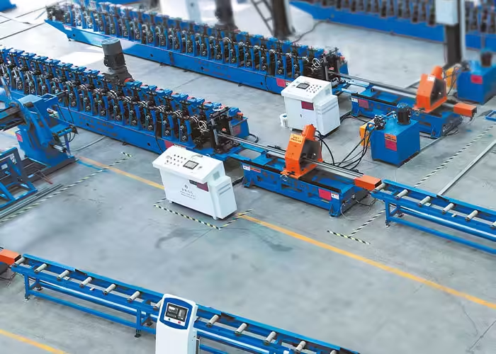
Roll forming gradually changes a flat strip into the required cross-section through multiple forming stations. Each roller stand performs only part of the total deformation. This progressive forming principle allows complex profiles to be produced continuously, but it also means that an error introduced at one station can influence every station that follows.
For example, if the strip enters the machine slightly off-center, later rollers may force one side of the material more aggressively than the other. If a roller is positioned too high or too low, the profile can accumulate uneven longitudinal stress. Material properties can also change from one coil to another, causing a previously stable setup to produce a different result.
The most common sources of roll forming defects can generally be grouped into four areas: material variation, tooling design, machine alignment, and operating conditions. In practice, several factors may occur at the same time, which is why troubleshooting should follow a systematic process rather than relying on a single adjustment.
1. Profile Twist
Twist occurs when the finished profile rotates gradually along its longitudinal axis instead of remaining in a consistent orientation. A short sample may appear acceptable, while a longer profile reveals a noticeable rotational change from one end to the other.
Twist is often associated with unequal forming forces on the two sides of the strip. If the left and right sections of the profile do not travel through the forming passes under similar conditions, residual stress can become unevenly distributed. Incorrect strip entry, asymmetric tooling, roller misalignment, inconsistent material thickness, or excessive forming pressure can all contribute to this problem.
The first step in troubleshooting is to confirm that the coil is entering the machine on the intended centerline. Entry guides should support the strip without forcing it sideways. Roller shafts and tooling positions should then be checked to determine whether both sides of the forming section are correctly aligned.
It is also important to examine where the twist first becomes visible. If the profile is already beginning to rotate halfway through the machine, adjusting only the final stands may hide the symptom temporarily without correcting the root cause.
2. Bow
Bow describes a profile that curves along its length when viewed from the side. Instead of remaining straight, the finished section bends upward or downward.
One common cause is unequal longitudinal stretching between different areas of the strip. During roll forming, some parts of the cross-section travel through longer deformation paths than others. Poor pass design or excessive deformation within a limited number of stands can increase this difference.
Bow may also result from incorrect roller height, uneven forming pressure, material residual stress, or problems in the straightening section. Downstream cutting can sometimes make the condition more noticeable because internal stresses are released when a continuous profile is separated into individual lengths.
When diagnosing bow, engineers should inspect the profile at several locations along the forming line. This helps determine whether the curvature develops during early forming, later calibration, straightening, or cutting.
Corrective action may involve redistributing the amount of forming between passes, checking upper and lower roller alignment, adjusting the straightening unit, or reviewing whether incoming material properties have changed.
3. Camber
Camber is a sideways curve along the length of the strip or finished profile. While bow is primarily visible from the side, camber causes the material to deviate laterally.
Incoming coil condition is an important factor. If the raw strip already contains camber, the roll forming line may not be able to completely remove it. Slitting quality can also influence strip straightness before the material reaches the forming machine.
Machine-related causes include off-center strip feeding, uneven side pressure, incorrectly positioned guides, and differences in roller contact between the two sides of the profile.
Operators should therefore inspect both the incoming strip and the finished profile. If camber exists before forming begins, attention should first be given to the raw material, slitting process, or leveling system. If straight material begins to curve only after entering the forming section, the cause is more likely related to machine setup or tooling.
4. Edge Wave
Edge wave appears as a series of ripples or waves along one or both edges of a formed profile. It is especially noticeable on profiles with wide flanges or relatively thin material.
The defect usually develops when an edge of the strip becomes longer than the adjacent material. Because the excess length cannot remain flat, it releases through local buckling and forms a wavy appearance.
Several process conditions can create this situation. The edge may be stretched excessively during bending, the forming sequence may introduce deformation too quickly, or roller geometry may place unnecessary longitudinal strain on the flange.
Material thickness and mechanical properties also influence sensitivity to edge wave. A machine setup that performs well with one coil may require evaluation when material specifications change.
Correcting edge wave often requires examining the entire pass sequence rather than tightening individual rollers. Excessive pressure can actually make the problem worse by increasing unwanted deformation. The objective is to allow the profile to develop progressively while controlling how strain is distributed across the strip.
5. End Flare
End flare occurs when the end of a cut profile opens, closes, or changes shape compared with the central portion of the part. The profile may run correctly while still connected to the continuous strip, but its geometry changes after cutting.
This happens because roll forming introduces internal stresses into the material. While the profile remains continuous, surrounding material helps restrain those stresses. Once the part is cut, some of the stress is released and the end moves toward a different shape.
End flare can be influenced by the forming sequence, material characteristics, final calibration, straightening, and cutting method. It is often more noticeable in asymmetrical or highly formed profiles.
Rather than compensating only at the final stand, engineers should determine how much residual stress is being introduced throughout the forming process. Improving the distribution of deformation across more passes can sometimes produce a more stable finished section.
For profiles where end geometry is particularly important, the cutting and post-forming stages should be evaluated together with the roll tooling rather than treated as completely separate processes.
6. Dimensional Variation
One of the most important roll forming defects from a quality-control perspective is dimensional variation. This may include changes in flange width, profile height, bend angle, hole position, overall width, or other specified dimensions.
Dimensional inconsistency can come from many sources because virtually every stage of the production line influences final geometry.
Typical factors include roller wear, shaft movement, incorrect roll gaps, inconsistent coil thickness, material springback, tooling setup, feed-length variation, and changes in operating conditions.
The first step should be to identify whether the variation is random or systematic. If every profile is consistently outside the required dimension in the same direction, tooling or setup is a likely area to investigate. If dimensions fluctuate continuously, material variation, mechanical looseness, feeding instability, or tooling wear may deserve closer attention.
Measurements should also be taken at several points along the production line whenever practical. Waiting until the final profile leaves the machine makes it much harder to identify where the dimensional deviation first developed.
Jinbolida’s forming machine solutions integrate progressive roll forming with production configurations that can include feeding, punching, cutting, and related automated operations, making coordinated control across these stages particularly important.
7. Surface Scratches and Tool Marks
Not every roll forming defect affects profile geometry. Surface damage can also make otherwise dimensionally acceptable parts unsuitable for their intended application.
Scratches, roller marks, dents, or coating damage may occur when foreign particles become trapped between the tooling and strip, roller surfaces become damaged, guides create excessive contact, or the material moves through the machine incorrectly.
Galvanized, coated, painted, stainless, and other appearance-sensitive materials may require particular attention because relatively small tooling defects can become visible on every finished profile.
When repeated marks appear at regular intervals, the spacing of those marks can provide useful diagnostic information. A recurring pattern may correspond with the circumference of a particular roller, helping operators locate damaged tooling.
Roller cleanliness should therefore be part of routine inspection. Burrs on incoming strip edges, loose metal particles, damaged guides, or worn tooling surfaces should be corrected before they create continuous surface defects.
Common Roll Forming Defects: Causes and Checks
| Defect | Typical Symptoms | Possible Causes | What to Check First |
|---|---|---|---|
| Twist | Profile rotates along its length | Uneven forming forces, misalignment, off-center feeding | Entry alignment and roller position |
| Bow | Profile curves upward or downward | Unequal longitudinal strain, straightening issues | Forming passes and straightener |
| Camber | Profile curves sideways | Incoming strip camber, guide pressure, uneven forming | Raw strip and centerline |
| Edge Wave | Flange edges become wavy | Excessive edge strain, poor pass progression | Pass design and flange deformation |
| End Flare | Profile ends open or close after cutting | Residual stress and springback | Final passes and cutting stage |
| Dimensional Variation | Width, angle, or height changes | Tool wear, material variation, setup instability | Roll gaps and material dimensions |
| Surface Damage | Scratches, dents, roller marks | Dirty or damaged tooling, guide contact | Roller and guide surfaces |
How Material Properties Affect Roll Forming Defects
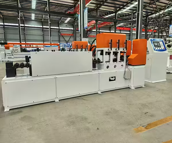
Machine adjustments are only part of the troubleshooting process. Incoming material can significantly affect the behavior of a roll forming line.
Yield strength, tensile strength, thickness, coating, hardness, and residual stress can influence how the strip responds to bending. Two coils with the same nominal dimensions may not behave identically if their mechanical properties differ.
Springback is a good example. After the material passes through a forming roll, it naturally attempts to recover part of its original shape. The amount of recovery depends partly on the material and partly on the geometry being formed. When material properties vary, bend angles may also vary unless the tooling and process provide sufficient control.
Strip width must also remain within the range required by the profile design. Incorrect width can change flange dimensions and alter how material flows through the rollers.
For this reason, when a previously stable production line suddenly develops defects, operators should not immediately assume that the machine has changed. Comparing the new coil with the previous material batch can provide important diagnostic information.
Why Roll Alignment Matters
Roll forming depends on a carefully controlled relationship between consecutive forming stations. Misalignment may appear small when measured at a single roller, but its effect can accumulate as the strip passes through multiple stands.
Shaft parallelism, horizontal positioning, vertical roll height, tooling spacers, and machine centerline should therefore be verified during setup and troubleshooting.
Operators should avoid using excessive roller pressure as a universal correction. Increasing pressure may temporarily change profile dimensions, but it can also introduce additional strain, accelerate tooling wear, mark the material surface, or create new defects elsewhere in the profile.
The goal is not simply to force material into shape. A stable forming process guides the material through a controlled sequence of bends so that each stand performs its intended portion of the total deformation.
Tooling Wear Can Create Gradual Quality Problems
Tooling-related defects do not always appear suddenly. Roller surfaces and contact areas can change gradually over extended production.
As wear increases, bend locations can shift slightly, roll gaps may effectively change, and material may no longer contact the tooling in exactly the same way as during the original setup.
This is one reason production records can be valuable. If dimensional measurements are tracked over time, gradual drift may become visible before parts move outside acceptable specifications.
Tooling inspection should include contact surfaces, edges, spacers, bearings, shafts, fasteners, and other components that influence roller position. The exact inspection interval depends on production conditions, material, machine design, and operating requirements.
A Better Troubleshooting Method
Random adjustments make roll forming defects harder to diagnose because changing several variables at once makes it difficult to identify which adjustment actually affected the result.
A more systematic approach begins by documenting the defect accurately. Determine whether it occurs continuously or intermittently, whether it appears on one side or both sides, and whether its severity changes with production speed or material.
Next, inspect the incoming strip before changing the machine. Confirm thickness, width, straightness, edge condition, and obvious coil damage.
The strip should then be followed through the machine stand by stand. Identifying the first location where the defect becomes visible often provides more useful information than examining only the finished part.
After locating the likely problem area, change one relevant variable at a time and record the result. This creates a repeatable troubleshooting process and reduces the risk of solving one defect while unintentionally creating another.
Preventing Roll Forming Defects Before Production Begins
The best troubleshooting strategy is to reduce the conditions that create defects in the first place.
A stable production process starts with a qualified profile drawing and a forming sequence designed around the actual material and geometry. Machine centerline, roller positions, strip guides, and tooling condition should be verified during setup.
Incoming material should be inspected against the required specification, especially when changing suppliers, material grades, thicknesses, or coil batches. Trial production can then be used to verify key profile dimensions before continuous manufacturing begins.
Production teams should also establish reference measurements for important dimensions. When those dimensions begin to drift, corrective action can be taken before large quantities of material are affected.
Maintenance and safety must remain part of the process. Forming rolls create in-running nip points and other machine hazards, so inspection and adjustment procedures should follow appropriate safeguarding and operating requirements. The U.S. Occupational Safety and Health Administration provides specific machine guarding guidance for forming rolls.
What Should Be Checked When Defects Appear?

When a roll forming line begins producing an abnormal profile, troubleshooting should move from upstream to downstream.
Start with the coil and verify material dimensions and condition. Next, confirm decoiling and leveling performance, followed by entry-guide alignment. Inspect the profile after successive roller stands to determine where deformation begins to deviate from the expected shape.
Once the forming section has been checked, evaluate downstream processes such as punching, straightening, cutting, and material handling. A defect visible at the end of the line is not always created by the roll forming stands themselves.
This process-oriented approach is especially important for automated production lines where several operations are integrated into one system.
Conclusion
Roll forming defects are rarely caused by one universal problem. Twist, bow, camber, edge wave, end flare, dimensional variation, and surface damage can develop from different combinations of material behavior, tooling geometry, machine alignment, pass progression, and operating conditions.
The most effective way to solve these problems is to identify where the defect first appears and then evaluate the process systematically. Checking incoming material, centerline alignment, roller condition, forming progression, and downstream operations provides a clearer diagnosis than repeatedly adjusting the final roller stands.
A properly configured roll forming process should control deformation progressively while maintaining stable material flow through every stage of production. For manufacturers developing new metal profiles or reviewing an existing forming process, equipment configuration should therefore begin with the finished profile drawing, material specification, processing sequence, and required quality characteristics.
FAQ
What are the most common roll forming defects?
Common roll forming defects include twist, bow, camber, edge wave, end flare, dimensional variation, and surface scratches or roller marks. Their causes may involve material condition, tooling, alignment, forming sequence, or machine setup.
What causes a roll formed profile to twist?
Twist is commonly associated with unequal forming forces across the profile. Off-center strip feeding, roller misalignment, asymmetric tooling, material variation, and uneven deformation can all contribute.
Can material changes cause roll forming defects?
Yes. Changes in thickness, yield strength, hardness, strip width, coating, or residual stress can alter how material behaves during forming. A machine setup that works with one coil may require verification when material properties change.
Why do roll formed parts change shape after cutting?
Internal stresses remain in the profile after forming. Cutting can release some of these stresses, causing the ends to open, close, twist, or flare. Forming sequence, material properties, calibration, and cutting conditions can all influence this behavior.
How can roll forming defects be reduced?
Defects can be reduced through consistent incoming-material control, correct strip alignment, properly designed forming passes, accurate roller setup, routine tooling inspection, controlled machine operation, and systematic quality measurement throughout production.
Need Help Evaluating a Roll Forming Process?
Every profile places different requirements on material feeding, tooling, forming stations, punching, cutting, and automation. If you are developing a new metal profile or evaluating a production line configuration, contact Jinbolida to discuss the profile drawing, material specifications, processing steps, and production requirements.
 English
  Arabic
  Russian
  Spanish
  French