
آلة تثقيب الأقواس الكهروضوئية: دقة فتحة التحكم
جدول المحتويات
مقدمة
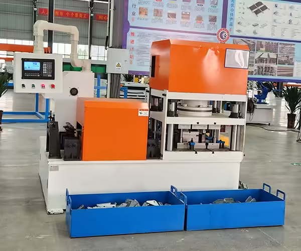
يمكن أن يكون لملف التثبيت الكهروضوئي أبعاد القناة C أو القناة U الصحيحة ويظل من الصعب تجميعه إذا تم وضع فتحات التثبيت الخاصة به بشكل غير صحيح. بالنسبة لقضبان الدعم الشمسية الطويلة التي تحتوي على العشرات من الثقوب المستديرة، أو الفتحات الطويلة، أو فتحات التوصيل، أو الثقوب الجانبية، فإن دقة التثقيب لا تقل أهمية عن دقة تشكيل المظهر الجانبي.
ويتمثل التحدي في أن دقة الثقب لا تعتمد على قالب التثقيب وحده.
أ آلة تثقيب القوس الكهروضوئية يحتاج إلى تنسيق تحديد موضع المواد، والتغذية المؤازرة، وشد الشريط، والتثبيت، وإزالة القالب، وتسلسل التثقيب، وردود فعل التشفير، وقوة المادة، ودرجة الحرارة، وموضع القطع، والتقطيع في العديد من خطوط الإنتاج لعملية تشكيل اللفة النهائية.
ويصبح هذا الأمر ذا أهمية متزايدة لأن تصنيع الطاقة الكهروضوئية يخدم نطاقًا أوسع من الأسواق وأشكال المشاريع. أفادت وكالة الطاقة الدولية للطاقة الكهروضوئية أنه تم تركيب ما يقرب من 698 جيجاوات من القدرة الكهروضوئية الجديدة على مستوى العالم في عام 2025 وأن 39 دولة قامت بتركيب ما لا يقل عن 1 جيجاوات خلال العام، مما يعزز التنويع المستمر لنشر الطاقة الكهروضوئية.
بالنسبة لمصنعي الأقواس، يمكن أن يعني المزيد من الأسواق المزيد من أبعاد الملف الشخصي، وواجهات التثبيت، وأنماط الفتحات، والمتطلبات الخاصة بالمشروع.
وبالتالي فإن السؤال الأكثر فائدة ليس ببساطة:
ما مدى دقة آلة التثقيب؟
إنه:
كيف يمنع نظام الإنتاج الكامل تراكم خطأ موضع الثقب من الفتحة الأولى إلى الفتحة الأخيرة للقوس الكهروضوئي النهائي؟
يشرح هذا الدليل مصدر هذه الأخطاء وما هي المعدات التي يجب على مشتري المعدات التحقق منها قبل اختيار نظام تثقيب الأقواس الكهروضوئية.
لماذا تعتبر دقة الثقب مهمة في إنتاج الأقواس الكهروضوئية
تربط هياكل التركيب الكهروضوئية العديد من المكونات الفردية.
اعتمادًا على تصميم النظام، يمكن استخدام الثقوب والفتحات من أجل:
- اتصالات السكك الحديدية،,
- اتصالات البريد،,
- مرفق المدادة،,
- الأقواس،,
- المشابك التثبيت،,
- السحابات،,
- لوحات الموصل،,
- تعديل الارتفاع،,
- وتحديد المواقع التثبيت.
تصف وزارة الطاقة الأمريكية هياكل التركيب الكهروضوئية بأنها أنظمة مستقرة ومتينة تحتاج إلى دعم المصفوفات مع مقاومة الظروف الخارجية بما في ذلك الرياح والتآكل على مدى فترات الخدمة الطويلة.
يتم تحديد التصميم الهيكلي الدقيق من قبل مهندس نظام التركيب، ولكن عملية التصنيع لا تزال بحاجة إلى إعادة إنتاج هذا التصميم باستمرار.
يمكن أن تؤثر فتحة التثبيت الموضوعة على بعد عدة ملليمترات من موقعها المقصود على كيفية اصطفاف المكونات أثناء التجميع.
يصبح هذا مهمًا بشكل خاص عندما تظل عدة أقواس يتم إنتاجها على آلات مختلفة أو في أوقات مختلفة قابلة للتبديل.
دقة الثقب هي أكثر من قياس واحد
عند مناقشة دقة التثقيب، يجب فصل عدة أبعاد مختلفة.
حجم الثقب
القطر الفعلي للفتحة المستديرة أو عرض وطول الفتحة.
الملعب المحلي
المسافة بين فتحتين متجاورتين.
الموقف التراكمي
العلاقة بين الثقب الأول والميزة أبعد بكثير على طول الملف الشخصي.
الموقف العرضي
المسافة بين الفتحة والخط المركزي أو الحافة الجانبية.
مسافة النهاية
المسافة بين الحفرة ونهاية القطع النهائية.
موقف ثقب إلى الانحناء
موقع الميزة المثقوبة بالنسبة إلى هندسة القناة C أو القناة U النهائية.
يمكن للآلة أن تؤدي أداءً جيدًا في فئة واحدة وتظل تخلق مشكلات في فئة أخرى.
على سبيل المثال، قد تبدو كل خطوة مجاورة مقبولة بينما تنتقل الفتحة الأخيرة تدريجيًا بعيدًا عن الموضع المقصود بسبب تراكم أخطاء تغذية صغيرة عبر ملف التعريف الكامل.
أهم أبعاد اللكم
| قياس | ما يتحكم فيه | مصدر الخطأ النموذجي |
|---|---|---|
| قطر الثقب | ملاءمة السحابة | حالة لكمة/موت |
| عرض الفتحة | توافق الاتصال | تآكل الأداة وتخليصها |
| طول الفتحة | نطاق التعديل | حالة الأدوات |
| الملعب حفرة | التباعد المحلي | التغذية المؤازرة |
| موقف الحفرة التراكمية | محاذاة الملف الشخصي بالكامل | تراكم الأعلاف |
| موقف عرضي | التمركز عبر الملف الشخصي | تتبع الشريط |
| نهاية المسافة | علاقة الجمعية | مزامنة القطع |
| المسافة من ثقب إلى انحناء | هندسة الاتصال النهائية | التثقيب + تشكيل لفة |
| ارتفاع الحفرة الجانبية | تجميع متعدد الوجوه | تحديد موضع الملف الشخصي |
ولذلك ينبغي تقييم آلة التثقيب ذات الأقواس الكهروضوئية الجيدة مقابل الرسم النهائي الفعلي بدلاً من قيمة دقة عنوان واحد.
كيف تتحكم التغذية المؤازرة في موضع الثقب
تُستخدم التغذية المؤازرة بشكل شائع لوضع الشريط قبل التثقيب.
يمكن لبرنامج الإنتاج تحديد تسلسل مثل:
تغذية 100 مم → لكمة → تغذية 50 مم → لكمة → تغذية 200 مم → لكمة
يتحكم المحرك المؤازر في حركة وحدة التغذية وفقًا للأمر المبرمج.
وهذا يوفر مرونة أكبر بكثير من الاعتماد فقط على درجة الصوت الميكانيكية الثابتة.
ومع ذلك، فإن المحرك الذي يحرك وحدة التغذية بمسافة مبرمجة لا يثبت تلقائيًا أن الشريط الفولاذي يتحرك بنفس المسافة تمامًا.
لا يزال من الممكن أن تتأثر الحركة المادية الفعلية بما يلي
- انزلاق الأسطوانة،,
- ضغط المغذية،,
- التوتر لفائف،,
- سطح المادة،,
- سمك الشريط،,
- تسارع،,
- توجيه المقاومة،,
- والتآكل الميكانيكي.
لهذا السبب، ترتبط دقة المؤازرة ودقة الفتحة النهائية ولكن لا ينبغي التعامل معها على أنها مواصفات متطابقة.
لماذا يمكن أن تصبح أخطاء التغذية الصغيرة مشاكل كبيرة
فكر في ملف تعريف مبسط يحتوي على 40 درجة ثقب متكررة.
إذا كانت كل دورة تغذية تختلف قليلاً عن الحركة المقصودة وكان الجهاز يشير دائمًا إلى الموضع السابق، فقد يتراكم الخطأ.
يمكن أن يصبح الاختلاف الصغير جدًا الذي يبدو غير مهم بين فتحتين متجاورتين أكثر وضوحًا بين:
الحفرة الأولى → الحفرة الأخيرة
ولهذا السبب ينبغي تقييم القضبان الكهروضوئية الطويلة باستخدام الأبعاد المحلية والطويلة المدى.
على سبيل المثال، يمكن مقارنة فحص الجودة
- الحفرة 1 إلى الحفرة 2
- الحفرة 10 إلى الحفرة 11
- الحفرة 1 إلى الحفرة 20
- الحفرة 1 إلى الحفرة 40
- الحفرة 1 لإنهاء القطع
وهذا يوفر صورة أوضح بكثير عما إذا كانت العملية تحتوي على خطأ تراكمي.
المرجع المطلق مقابل التغذية المتزايدة المتكررة
إحدى الطرق التي يمكن لأنظمة الإنتاج من خلالها تقليل الأخطاء التراكمية هي التحكم في الميزات المهمة من مراجع محددة بدلاً من السماح لكل موضع لاحق بالاعتماد كليًا على جميع دورات التغذية السابقة.
تعتمد طريقة التحكم الدقيقة على تصميم الماكينة.
المبدأ هو أن الميزات المهمة يجب أن تكون مرتبطة بمواضع مرجعية ذات معنى مثل:
- بداية المنتج،,
- موضع المادة المقاسة،,
- مرجع التشفير،,
- أو نقطة مرجعية أخرى تم التحقق منها.
بالنسبة للمشترين، يؤدي هذا إلى سؤال مهم:
كيف تتحكم الآلة في خطأ تحديد الموضع التراكمي عبر شريحة كهروضوئية طويلة؟
لا تقبل فقط إجابة حول دقة المحرك المؤازر.
اسأل عن كيفية التحقق من نظام تحديد موضع المواد بالكامل.
يمكن أن تؤدي تعليقات التشفير إلى تحسين مراقبة الموقع
يمكن استخدام جهاز التشفير لقياس الحركة داخل نظام الإنتاج.
اعتمادا على التصميم، قد يراقب:
- دوران المغذية،,
- قياس حركة العجلة،,
- السفر المادي،,
- أو موضع الملف الشخصي المصب.
يمكن أن تساعد معلومات التشفير نظام التحكم في مقارنة الحركة المطلوبة مع الحركة المقاسة.
ومع ذلك، فإن تثبيت التشفير نفسه مهم.
على سبيل المثال، يمكن لعجلة القياس أن توفر معلومات غير دقيقة إذا كانت:
- زلات،,
- يفقد الاتصال،,
- تصبح ملوثة،,
- يرتدي،,
- أو يتم الضغط عليه بشكل غير صحيح على الشريط.
ولذلك ينبغي اختبار جهاز التغذية المرتدة في ظل ظروف مادية حقيقية وليس فقط أثناء التشغيل بدون تحميل.
يجب التحكم في ضغط أسطوانة التغذية

تحتاج بكرات التغذية المؤازرة إلى قوة اتصال كافية لتحريك المادة باستمرار.
الضغط القليل جدًا يمكن أن يسمح للشريط بالانزلاق.
يمكن أن يؤدي الضغط الزائد إلى حدوث مشكلات أخرى، خاصة مع المواد المجلفنة أو المطلية.
الضغط المفرط قد يساهم في:
- وضع العلامات على السطح،,
- التشوه المحلي،,
- ارتداء الأسطوانة،,
- وحمل محرك غير ضروري.
إذا انزلق الشريط بشكل متكرر، فلا ينبغي أن يكون الضغط المتزايد هو الخطوة الوحيدة لاستكشاف الأخطاء وإصلاحها.
يجب على المشغلين أيضًا التفتيش:
- مقاومة ديكويلر،,
- إعدادات المستوي،,
- حلقة الشريط،,
- التلوث السطحي،,
- حالة الأسطوانة،,
- والتسارع.
تعتمد التغذية المستقرة على قسم الإدخال بأكمله.
يمكن أن يؤثر شد الملف على موضع التثقيب
يجب أن تقوم وحدة التغذية بوضع الشريط، لكن المعدات الأولية يمكن أن تؤثر على مدى صعوبة تحديد الموضع.
إذا كانت وحدة التغذية المؤازرة تسحب بقوة بشكل مستمر ضد أداة فك اللفائف أو أداة التسوية، فقد تصبح حركة المادة الفعلية أقل تكرارًا.
ولذلك يجب أن يقوم خط إنتاج مستقر بإدارة المواد بين:
أداة فك اللف → التسوية → المخزن المؤقت/الحلقة → التغذية المؤازرة → التثقيب
وفقا لهندسة المعدات.
يجب أن يتحكم المؤازرة في تحديد المواقع بدلاً من محاربة التوتر المنبع غير المتوقع أثناء كل ضربة.
بالنسبة لأنماط الثقوب عالية الدقة، تصبح هذه العلاقة ذات أهمية خاصة.
عناصر التحكم في تتبع الشريط، موضع الثقب المستعرض
تحديد المواقع الطولية هو جزء واحد فقط من دقة الثقب.
يحتاج الشريط أيضًا إلى البقاء في المنتصف بشكل صحيح عبر عرضه.
إذا تحركت بشكل جانبي قبل الدخول إلى القالب، فيمكن أن تتحول الحفرة بالنسبة إلى الخط المركزي النهائي.
هذا يمكن أن ينتج:
- مسافة حافة غير متساوية،,
- فتحات خارج المركز،,
- موضع الموصل غير صحيح،,
- والأقواس النهائية غير المتماثلة.
لذلك يجب أن تحافظ أدلة الدخول على موضع الشريط دون إجبار المادة بقوة على جانب واحد.
إذا كان الشريط يضغط باستمرار على دليل واحد، فيجب على المشغلين التحقق من خط الوسط العلوي وحالة الملف.
يمكن أن يبدو اختلاف عرض المادة وكأنه خطأ في التثقيب
لنفترض أن الثقب مثقوب في موضع ثابت تمامًا بالنسبة إلى الخط المركزي للآلة.
إذا تغير عرض الشريط الوارد، تتغير أيضًا المسافة من تلك الفتحة إلى حافة المادة.
قد يقوم المفتش الذي يقيس من حافة الشريط بالإبلاغ عن خطأ في موضع الثقب.
ربما لم تتحرك آلة التثقيب نفسها.
وهذا يوضح سبب الحاجة إلى تحديد مسندات الأبعاد بوضوح.
يجب على الشركات المصنعة تحديد ما إذا كان يتم التحكم في موضع الثقب من:
- قطاع الخط المركزي،,
- حافة مرجعية واحدة،,
- حافة الملف الشخصي النهائية،,
- مركز الويب،,
- أو مسند آخر.
يجب أن تتطابق طرق القياس مع رسم المنتج.
تؤثر إزالة اللكمة والقالب على جودة الثقب
تصبح دقة الموضع بلا معنى إذا كان الثقب نفسه سيئ التكوين.
تؤثر إزالة اللكمة والقالب على عملية القص.
التخليص غير المناسب يمكن أن يساهم في:
- لدغ المفرط،,
- جودة حافة رديئة،,
- تسارع تآكل الأداة،,
- حمل اللكم العالي،,
- وهندسة الثقب غير المنتظمة.
يعتمد التخليص المناسب على خصائص المواد وتصميم الأدوات.
ولذلك ينبغي أن يتم إنشاؤها للمحدد:
- درجة الصلب،,
- سمك،,
- طلاء،,
- وتتميز بالهندسة.
إن التغيير إلى فولاذ أقوى أو أكثر سمكًا يمكن أن يبرر مراجعة ظروف التثقيب بدلاً من افتراض أن الإعداد السابق يظل الأمثل.
الفولاذ عالي القوة يغير ظروف التثقيب
يحتاج مصنعو الأقواس الكهروضوئية بشكل متزايد إلى التفكير فيما هو أبعد من سمك المادة وحدها.
يمكن أن يكون لشريطين بنفس السُمك الاسمي خواص ميكانيكية مختلفة.
تخلق المواد ذات القوة العالية عمومًا متطلبات أكبر على قوة التثقيب والأدوات.
ولذلك ينبغي تحديد الخط باستخدام:
درجة المادة + سمك + محيط الثقب + عدد اللكمات المتزامنة
بدلا من سمك وحده.
يصبح هذا مهمًا بشكل خاص مع الأنظمة متعددة المحطات حيث يمكن معالجة العديد من الميزات خلال دورة واحدة.
الآلة القادرة على ثقب ثقب دائري واحد في فولاذ معين لا تتمتع تلقائيًا بنفس هامش العملية عندما يتم ثقب عدة فتحات طويلة في وقت واحد.
الفتحات الطويلة أكثر تطلبًا من الثقوب المستديرة البسيطة
تحتوي المقاطع الكهروضوئية في كثير من الأحيان على فتحات ممدودة لأنها توفر تعديل التجميع.
تقدم الفتحة عدة أبعاد للجودة:
- عرض،,
- طول،,
- نهاية نصف القطر،,
- التوجه،,
- الوضع الطولي،,
- والموضع العرضي.
يمكن أن يؤثر محيط القطع الأكبر أيضًا على حمل التثقيب مقارنةً بالفتحة المستديرة الصغيرة.
إذا تآكلت أدوات الفتحات، فقد يرى المصنعون ما يلي
- لدغ أكبر،,
- تنتهي الفتحة السيئة،,
- تغيير الأبعاد،,
- أو زيادة قوة اللكم.
عند مقارنة معدات التثقيب ذات الأقواس الكهروضوئية، قم بتوفير رسومات الثقب والفتحة الحقيقية بدلاً من ذكر عدد محطات التثقيب المطلوبة فقط.
لماذا لا تعني المزيد من محطات التثقيب معدات أفضل تلقائيًا
JBLDIE معدات تثقيب الرفوف الكهروضوئية الشمسية يتضمن النطاق تكوينات تثقيب ثلاثية وستة وتسع محطات لمتطلبات معالجة مختلفة.
يجب أن يتبع عدد المحطات تعقيد المنتج.
قد تكون الآلة ذات الثلاث محطات كافية عندما تتطلب الدعامة مجموعة محدودة من أنماط الثقوب المتكررة.
تصبح المزيد من المحطات مفيدة عندما يحتوي المكون على:
- عدة أنواع من الثقوب،,
- مجموعات فتحات مختلفة،,
- أسطح معالجة متعددة،,
- أو تسلسلات أكثر تعقيدا.
تسع محطات لا تتفوق تلقائيًا على ثلاث محطات.
تضيف المحطات غير المستخدمة تعقيدًا للمعدات دون زيادة قيمة الإنتاج الفعلية.
يجب أن يحدد رسم المنتج بنية التثقيب.
عندما يضيف التثقيب متعدد المحطات قيمة حقيقية
يصبح النظام متعدد المحطات ذا قيمة عندما تظل الأدوات المختلفة مثبتة وجاهزة لعدة مواصفات بين قوسين.
This can reduce repeated die changes.
For example, separate stations might be configured for:
- فتحات تثبيت مستديرة،,
- فتحات ممدودة،,
- connector holes,
- side holes,
- and special project features.
The production recipe can then activate the required operations.
This can support factories that regularly switch between several related PV bracket specifications.
However, buyers should ask whether unused stations create additional material-handling or cycle limitations.
The machine should remain efficient for both simple and complex products.
يجب تضمين منتج التثقيب الأبطأ في تخطيط السعة
A common mistake is to calculate production capacity using the easiest bracket.
Consider two six-meter C-channels.
Channel A
Contains 12 simple holes.
Channel B
Contains 50 holes and slots using several stations.
The forming length is identical.
The punching workload is not.
Channel B may determine the real production bottleneck.
Equipment buyers should therefore identify:
- highest hole count,
- most complex pattern,
- strongest material,
- thickest material,
- and shortest batch size
before estimating practical line output.
يجب قياس وقت الدورة لكل منتج نهائي
Maximum feed speed can be useful, but finished-part cycle time gives a clearer production picture.
A complete punching cycle can include:
- feed,
- deceleration,
- positioning,
- clamping where applicable,
- punch down,
- punch return,
- scrap release,
- next feed.
For complex products, this sequence repeats many times.
The production calculation should use the full sequence rather than the travel speed of the servo axis alone.
اللكم قبل تشكيل لفة
Many PV bracket production lines punch flat strip before forming.
This provides several advantages.
The flat material is easy to support.
Punching tools have straightforward access.
Scrap can be removed before the strip reaches the forming rolls.
Servo feeding can also coordinate several different longitudinal patterns.
A typical sequence may be:
decoiling → leveling → servo feeding → punching → roll forming → cutting
This configuration can be particularly efficient for high-volume C- and U-channel production.
However, the final hole position should still be inspected after forming.
لماذا يمكن للتشكيل أن يغير العلاقة بين الثقوب المثقوبة
Suppose a slot is punched close to a future bend.
When the strip is later bent:
- the surrounding material moves,
- the surface changes orientation,
- springback occurs,
- and finished profile geometry develops.
The hole may remain exactly where it was punched in the strip, but its relationship with the final C-channel dimensions can change.
This is why finished inspection should measure:
hole position relative to the completed profile
instead of relying only on:
flat strip position before forming.
The closer a hole is to a bend or deformation zone, the more important this becomes.
يستخدم ما بعد اللكم مرجعًا مختلفًا
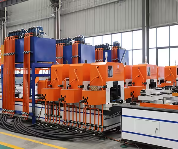
Some photovoltaic components can be punched after they are formed.
This allows the tooling to reference the finished three-dimensional section more directly.
However, it introduces other challenges.
The punch fixture must support the profile without crushing it.
Tool access may be limited by:
- flanges,
- lips,
- deep channels,
- and nearby features.
The best solution depends on the product.
Pre-punching is not automatically better because it is easier.
Post-punching is not automatically better because it references the final section.
The drawings and production volume should determine the sequence.
يتطلب التثقيب الجانبي وضعًا ثابتًا للملف الشخصي
Some brackets contain holes on more than one surface.
For example, a formed C-channel may require:
- web holes,
- flange holes,
- or side connection features.
When punching a formed profile, the machine needs to establish a repeatable three-dimensional position.
A small variation in:
- افتتاح القناة،,
- زاوية شفة،,
- تطور،,
- or support position
can change where the side punch contacts the profile.
This means forming accuracy and punching accuracy become directly connected.
An unstable upstream profile makes accurate multi-face punching more difficult.
تحتاج مكونات الموصل إلى استراتيجية تثقيب مختلفة
Not every photovoltaic support component is a long rail.
Mounting structures also use smaller:
- موصلات،,
- brackets,
- plates,
- and joining components.
These parts may require punching, cutting, and bending within a shorter production cycle.
JBLDIE’s photovoltaic bracket equipment portfolio includes connector-processing equipment in addition to long-profile forming systems. Its broader آلة تشكيل أقواس الخلايا الشمسية الكهروضوئية category includes both C/U profile equipment and connector-related machinery.
Long profiles and small components should therefore not always share the same production strategy.
Separating these processes can improve line balance when their cycle requirements are very different.
يؤثر مزامنة القطع على موضع الثقب النهائي
Even if every hole is correctly positioned relative to the material, a finished bracket can still fail its drawing if the cutter separates the profile at the wrong position.
Consider a profile requiring:
50 mm from first hole to leading end
50 mm from last hole to trailing end
Hole punching and cutting now share the same dimensional chain.
If the cutter drifts by several millimeters, the hole pattern appears shifted relative to the finished part.
For this reason, end distances should be measured after cutting.
The troubleshooting process should distinguish between:
- incorrect punching,
- incorrect feeding,
- and incorrect cutting.
ينبغي تنسيق التشفير ومرجع القطع
Some lines use separate positioning information for punching and cutting.
Others use shared material-position data.
Whichever architecture is selected, the two systems need a consistent dimensional reference.
Otherwise, the hole pattern can remain stable while finished end distance varies.
Commissioning should therefore include several products with known:
- موقف الحفرة الأولى،,
- موقف الحفرة الأخيرة،,
- overall length,
- and cut-end allowance.
This tests whether punching and cutting operate as one coordinated production system.
منع خطأ الثقب التراكمي
A practical control strategy can include several layers.
التحقق من المواد الواردة
Check width, thickness, grade, and strip condition.
تثبيت قسم الدخول
Avoid excessive upstream tension or uncontrolled strip movement.
ضبط ضغط وحدة التغذية بشكل صحيح
Prevent slip without marking or deforming the strip.
التحقق من حركة المؤازرة
Compare programmed movement against actual finished dimensions.
استخدم تعليقات الموقف
Monitor material movement using appropriate encoder or measuring systems.
حالة أدوات التحكم
Prevent punch wear from changing hole dimensions.
فحص الموقف بعيد المدى
Measure first-to-last-hole relationships, not only neighboring pitch.
قطع الإحداثيات
Check hole pattern against finished cut ends.
القياس بعد التشكيل
Confirm the final bracket rather than only the flat strip.
This multi-stage approach is more reliable than attempting to solve every problem through servo calibration.
جدول استكشاف الأخطاء وإصلاحها العملي لدقة الثقب
| Symptom | سبب محتمل | الفحص الأول |
|---|---|---|
| Every hole shifted equally | Incorrect datum or starting position | Product zero/reference |
| Pitch varies randomly | Strip slip or feeder instability | Servo feeder and tension |
| Error increases along profile | Cumulative feed error | Long-range feed measurement |
| Holes shift sideways | تتبع الشريط | Guides and centerline |
| Hole size changes | Punch/die wear | حالة الأدوات |
| Burr increases | Clearance or tool wear | لكمة والموت |
| Slot distorted after forming | Too close to bend | فحص الملف الشخصي النهائي |
| First hole correct, last hole wrong | تراكم الأعلاف | Encoder/reference logic |
| Hole pattern correct, end distance wrong | Cutting error | Cutter synchronization |
| Side holes vary | Profile position unstable | Forming and fixture |
| Error starts after coil change | Material/feeding condition | New coil specification |
كيفية استكشاف الأخطاء التراكمية وإصلاحها
When the last holes of a profile drift but the first hole remains correct, do not immediately adjust the die.
The die determines hole shape.
The problem is more likely related to material positioning.
Begin by producing several parts using the same program.
Measure the error at several locations:
- 500 mm,
- 1,000 mm,
- 2,000 mm,
- 4,000 mm,
- and final position.
If error increases consistently with length, investigate:
- servo calibration,
- measuring-wheel condition,
- زلة المغذية،,
- encoder feedback,
- and control-reference logic.
If the error appears randomly rather than progressively, inspect material movement and mechanical stability.
التكرار والدقة ليسا نفس الشيء
A machine can be repeatable but inaccurate.
For example, every finished profile may place the first slot exactly 3 mm away from the intended position.
That is a calibration or reference issue.
A machine can also be accurate on average but poorly repeatable.
One profile may be +2 mm, the next -2 mm, and the next +1 mm.
That suggests process instability.
Equipment acceptance should therefore evaluate both:
دقة
How close the mean result is to the target.
و
التكرار
How consistently multiple parts reproduce the same result.
A single perfect sample cannot demonstrate repeatability.
ينبغي قياس عدة ملفات تعريف متتالية
During FAT or commissioning, do not inspect only one bracket.
Produce several consecutive finished components.
يقيس:
- موقف الحفرة الأولى،,
- selected internal pitches,
- final-hole position,
- end distance,
- قطع الطول،,
- الوضع العرضي،,
- and relevant profile dimensions.
If all parts show nearly the same deviation, calibration may be needed.
If deviations vary significantly between parts, process stability should be investigated.
This distinction saves time during troubleshooting.
يجب أن تستخدم الدهون نمط الثقب الحقيقي
A punching machine can look impressive when repeatedly punching one simple hole.
That test provides limited information if the buyer’s actual product contains:
- several long slots,
- multiple hole diameters,
- side holes,
- and different spacing.
A meaningful Factory Acceptance Test should use a representative product drawing.
Buyers should provide one of the more demanding patterns rather than the easiest one.
The test should verify:
- تسلسل اللكم،,
- material feeding,
- hole quality,
- cumulative position,
- production cycle,
- and finished-part repeatability.
ما الذي يجب على المشترين طرحه أثناء FAT
الأسئلة المفيدة تشمل:
- What is the material grade used during the test?
- Is the thickness representative of normal production?
- Are actual slots and hole groups being punched?
- How is the first material position established?
- How is cumulative error monitored?
- What device measures actual material movement?
- How many consecutive profiles will be inspected?
- How is hole position measured?
- How is cut-end position synchronized?
- What happens after a product recipe change?
These questions provide more useful information than watching the machine complete a short demonstration cycle.
ثلاث أو ست أو تسع محطات: ابدأ بالرسم
PV bracket punching equipment is often compared by the number of stations.
A better selection method begins with the hole matrix.
List every required feature:
| ميزة | المنتج أ | المنتج ب | المنتج ج |
|---|---|---|---|
| Round web hole | ✓ | ✓ | ✓ |
| Long web slot | ✓ | ✓ | ✓ |
| Side hole | ✓ | ✓ | |
| Large connector hole | ✓ | ||
| Alternative slot | ✓ | ✓ | |
| Special project feature | ✓ |
Then determine which tools need to remain installed simultaneously.
A three-station system may be enough for the first product family.
More stations become useful as the feature matrix expands.
The machine configuration should follow production needs rather than the idea that the largest station count is automatically the most advanced.
المزيد من المحطات يمكنها تحسين مرونة التحول
The strongest reason for additional stations is often not raw punching speed.
It can be tooling availability.
If several dies remain mounted on separate stations, the machine may switch between products through:
- program selection,
- feeding changes,
- station activation,
- and limited mechanical adjustment
rather than removing and reinstalling dies every time.
This becomes valuable for factories serving multiple solar projects with shorter production batches.
The real benefit should therefore be measured through:
last qualified Product A → first qualified Product B
not simply by counting hydraulic cylinders.
نمو سوق الطاقة الكهروضوئية الحالي يزيد من قيمة المرونة
IEA PVPS reported that global PV capacity approached 3 TW by the end of 2025, while deployment continued spreading across a wider number of national markets.
This does not mean every bracket manufacturer automatically needs maximum equipment flexibility.
Dedicated lines can remain highly efficient for stable high-volume products.
However, manufacturers supplying several projects or export markets may need to manage more:
- profile types,
- أنماط الاتصال،,
- أبعاد الفتحة،,
- finished lengths,
- and material specifications.
For these factories, programmable punching and repeatable changeover become strategically more important than maximum station count alone.
دقة التثقيب وحماية السطح المجلفن
Many photovoltaic support profiles use galvanized steel.
Punching breaks through the coated sheet and creates a new cut edge.
At the same time, feeding and clamping can mark the broad coated surface if they are not controlled properly.
The U.S. Department of Energy notes that steel and other metal components in PV racking systems can be exposed to corrosion and that material combinations and protective systems need to be considered carefully in harsh environments.
From a manufacturing perspective, the punching line should therefore avoid unnecessary coating damage around areas unrelated to the intended cut.
يفحص:
- feeder rollers,
- المشابك،,
- أدلة،,
- support tables,
- scrap,
- and finished-product handling.
Punching accuracy and surface quality should be inspected together.
يمكن أن تؤثر إزالة الخردة على الموثوقية
Every punching operation produces material that needs to leave the tool safely.
Slugs and scrap that remain around the die can create:
- tool jams,
- علامات السطح،,
- double punching,
- sensor alarms,
- or tooling damage.
High-hole-density PV profiles generate more scrap over the same profile length.
Scrap management should therefore be considered during equipment selection.
يسأل:
- Where do slugs go?
- How are they discharged?
- Can scrap accumulate inside the machine?
- Is the area easy to clean?
- Can sensors detect an abnormal tool condition?
A reliable punching system needs an equally reliable waste path.
يجب أن تعتمد صيانة الأداة على جودة المنتج
Punches and dies are wearing components.
Maintenance should not wait until a tool breaks completely.
Finished parts often show early signs of deterioration.
Useful indicators include:
- increasing burr,
- changing slot dimensions,
- rough edges,
- greater punching noise,
- rising load,
- incomplete slug release,
- or more frequent jams.
Production teams can record tool cycles and inspection results.
This helps connect preventive maintenance with actual component quality.
إدارة الوصفات للأقواس الكهروضوئية المتعددة
A programmable punching system can store different product recipes.
A recipe may contain:
- first-hole location,
- hole sequence,
- خطوة،,
- active stations,
- قطع الطول،,
- product quantity,
- and other production settings.
This can reduce manual re-entry when repeat products return.
However, a stored recipe should not automatically be trusted after:
- tooling replacement,
- feeder maintenance,
- encoder change,
- material change,
- or major machine adjustment.
A first-piece check remains necessary.
Digital repeatability depends on mechanical repeatability.
يمكن أن تساعد إمكانية التتبع في تشخيص مشاكل الثقب
Factories serving demanding projects may benefit from connecting production records with material and machine information.
A useful production record can contain:
- coil number,
- درجة المواد،,
- سمك،,
- product recipe,
- punching-tool set,
- production date,
- dimensional inspection,
- and machine alarms.
Suppose cumulative hole error begins during one shift.
The records can help determine whether the issue coincided with:
- a new coil,
- tool maintenance,
- recipe change,
- تعديل المغذية،,
- or another event.
Data becomes useful when it supports troubleshooting rather than simply increasing the number of values displayed on an HMI.
كيفية تقييم آلة تثقيب الأقواس الكهروضوئية
Before equipment selection, buyers should prepare complete product drawings.
Then ask the supplier to explain the production process around those drawings.
الأسئلة الهامة تشمل:
- How many unique hole types are required?
- Which holes can be punched simultaneously?
- Which stations remain installed during changeover?
- How is material position measured?
- كيف يتم التحكم في خطأ التغذية التراكمي؟
- How is lateral strip movement controlled?
- What material grade is included in the machine calculation?
- How does punching force change with stronger steel?
- How are slots and round holes inspected?
- How is punching coordinated with cutting?
- How is final hole-to-bend position verified?
- كيف تتم إزالة الخردة؟
- How are tools maintained?
- What representative product will be used during FAT?
The quality of these answers is more important than a single advertised precision figure.
ما هي المعلومات التي يجب تقديمها قبل تكوين الجهاز؟
A complete technical package should include:
مادة
يقدم:
- درجة الصلب،,
- yield strength where relevant,
- سمك،,
- عرض الشريط،,
- طلاء،,
- coil size.
رسم الحفرة
يقدم:
- round-hole diameters,
- أبعاد الفتحة،,
- hole groups,
- longitudinal positions,
- transverse positions,
- side holes,
- tolerances.
الملف الشخصي النهائي
يقدم:
- C/U/Z profile geometry,
- الانحناءات،,
- lips,
- finished width,
- finished length.
إنتاج
يقدم:
- annual volume,
- common batch size,
- تردد التحول،,
- وقت الدورة المطلوبة،,
- expected product mix.
جودة
Define:
- local pitch tolerance,
- cumulative positioning requirement,
- end distance,
- حجم الثقب،,
- burr requirement,
- and surface expectations.
This allows the punching system to be engineered around actual production instead of a generic station count.
قائمة مرجعية عملية لقبول المشتري
Before approving a PV bracket punching machine, verify:
Material Feeding
The strip moves consistently without visible slip or uncontrolled lateral movement.
Hole Quality
Round holes and slots meet the required shape and edge condition.
الملعب المحلي
Adjacent features remain within the agreed requirement.
الموقف التراكمي
Long-range hole location remains stable.
الموقف العرضي
Features remain correctly centered relative to the reference datum.
Finished Profile Position
Punched features remain correct after roll forming.
مسافة النهاية
The cutter separates the profile at the intended position.
التكرار
Several consecutive products show consistent results.
التحول
Stored recipes and tooling changes reproduce the next product correctly.
جودة السطح
Feeders, guides, and tooling do not create unnecessary coating damage.
Scrap Removal
Punching waste leaves the tool reliably.
Fault Diagnostics
Operators can identify feeder, punch, sensor, and positioning errors clearly.
خاتمة
أ آلة تثقيب القوس الكهروضوئية should be evaluated as a complete positioning and processing system rather than simply a hydraulic press with several dies.
Accurate holes depend on the relationship between servo feeding, strip tracking, material tension, encoder feedback, tooling condition, punching sequence, material properties, roll forming, and final cutting.
For long photovoltaic support profiles, cumulative error deserves particular attention.
A machine may produce acceptable local hole pitch while still allowing the final holes to drift relative to the beginning of the profile. Buyers should therefore measure both short-range and long-range dimensions during machine acceptance.
The number of punching stations should also be selected from the actual product matrix. Three, six, or nine stations only create value when the installed tools correspond with the bracket family’s real hole patterns and reduce practical changeover work.
As PV deployment continues expanding into more markets, manufacturers serving several projects may increasingly benefit from programmable feeding, flexible station configuration, stored recipes, repeatable changeover, and stronger production traceability.
The best equipment selection begins with the finished bracket drawing—not with a machine specification sheet.
التعليمات
ما هي آلة التثقيب PV؟
A PV bracket punching machine is equipment used to create round holes, slots, connector openings, and other features in photovoltaic mounting components. It can work with flat strip, formed profiles, or integrated roll forming production lines.
ما الذي يسبب خطأ تراكمي في موضع الثقب في الأقواس الكهروضوئية؟
Possible causes include servo-feed calibration, strip slip, encoder error, unstable feeder pressure, upstream tension, mechanical wear, or control-reference problems. Long-range measurements are needed to distinguish cumulative error from local pitch variation.
هل آلة التثقيب ذات التسع محطات أفضل من آلة التثقيب ذات الثلاث محطات؟
Not automatically. The correct station count depends on the number of hole types, processing surfaces, product variations, and changeover requirements. A simpler product may not benefit from unused stations.
هل يجب ثقب فتحات الأقواس الكهروضوئية قبل أو بعد تشكيل اللفة؟
Both approaches are possible. Pre-punching provides easier tool access, while post-punching can reference finished profile geometry more directly. The correct sequence depends on hole location, profile shape, tolerance, volume, and tooling access.
ما الذي يجب على المشترين اختباره أثناء آلة التثقيب الكهروضوئية FAT؟
Buyers should test representative material and actual hole patterns while checking hole dimensions, local pitch, cumulative position, transverse location, cut-end distance, production cycle, repeatability, and changeover performance.
هل تحتاج إلى تكوين معدات تثقيب الأقواس الكهروضوئية؟
The punching system should be developed from your actual bracket profile, material grade, thickness, round holes, slots, side features, cumulative positioning requirements, production volume, and changeover needs. اتصل بـ JBLDIE to discuss your photovoltaic bracket drawings and punching requirements.
 Arabic
  English
  Russian
  Spanish
  French