
Perforadora de soporte fotovoltaico: precisión del orificio de control
/ Punzonadora de soporte fotovoltaico: precisión del orificio de control
Tabla de contenido
Introducción
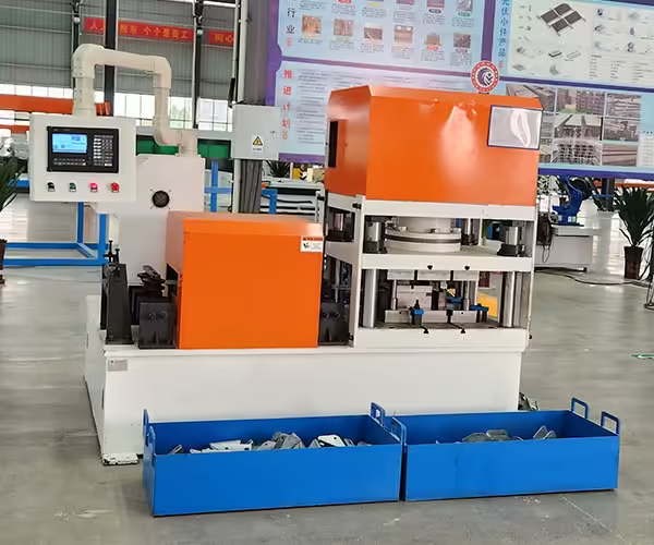
Un perfil de montaje fotovoltaico puede tener las dimensiones correctas del canal C o del canal U y aún así resultar difícil de montar si sus orificios de montaje están colocados incorrectamente. Para carriles de soporte solares largos que contienen docenas de orificios redondos, ranuras alargadas, aberturas de conexión o orificios laterales, la precisión del punzonado es, por lo tanto, tan importante como la precisión de la formación del perfil.
El desafío es que la precisión del agujero no depende únicamente del troquel de punzonado.
A Perforadora de soportes fotovoltaicos necesita coordinar el posicionamiento del material, la servoalimentación, la tensión de la tira, la sujeción, la holgura del troquel, la secuencia de punzonado, la retroalimentación del codificador, la resistencia del material, la temperatura, la posición de corte y, en muchas líneas de producción, el proceso de conformado por rodillos posterior.
Esto se vuelve cada vez más importante a medida que la fabricación fotovoltaica atiende a una gama más amplia de mercados y formatos de proyectos. IEA PVPS informó que se instalaron aproximadamente 698 GW de nueva capacidad fotovoltaica a nivel mundial en 2025 y que 39 países instalaron al menos 1 GW durante el año, lo que refuerza la diversificación continua del despliegue fotovoltaico.
Para los fabricantes de soportes, más mercados pueden significar más dimensiones de perfil, interfaces de montaje, patrones de orificios y requisitos específicos del proyecto.
Por tanto, la pregunta más útil no es simplemente:
¿qué precisión tiene la punzonadora?
Este:
¿Cómo evita que se acumule el error de posición del orificio desde el primer orificio hasta el último orificio del soporte fotovoltaico terminado?
Esta guía explica dónde se originan esos errores y qué equipos deben verificar los compradores antes de seleccionar un sistema de punzonado de soportes fotovoltaicos.
Por qué es importante la precisión de los agujeros en la producción de soportes fotovoltaicos
Las estructuras de montaje fotovoltaico conectan muchos componentes individuales.
Dependiendo del diseño del sistema, se pueden utilizar agujeros y ranuras para:
- conexiones ferroviarias,
- post conexiuni,
- accesorio de correa,
- brackets,
- montarea păturii,
- sujetadores,
- placas conectoras,
- ajustare de înaltă,
- y posicionamiento de instalación.
El Departamento de Energía de EE. UU. describe las estructuras de montaje fotovoltaico como sistemas estables y duraderos que necesitan soportar conjuntos y al mismo tiempo resistir condiciones exteriores, como el viento y la corrosión, durante largos períodos de servicio.
El diseño estructural exacto lo determina el ingeniero del sistema de montaje, pero el proceso de fabricación aún necesita reproducir ese diseño de manera consistente.
Una ranura de montaje colocada a varios milímetros de su ubicación prevista puede afectar la forma en que se alinean los componentes durante el ensamblaje.
Esto resulta especialmente importante cuando varios soportes producidos en diferentes máquinas o en diferentes momentos deben permanecer intercambiables.
La precisión del agujero es más de una medida
Cuando se habla de precisión de punzonado, se deben separar varias dimensiones diferentes.
Tamaño del orificio
El diámetro real de un orificio redondo o el ancho y largo de una ranura.
Campo local
La distancia entre dos hoyos vecinos.
Posición acumulada
La relación entre el primer agujero y una característica mucho más avanzada en el perfil.
Posición transversal
La distancia entre el agujero y la línea central o borde lateral del perfil.
Distancia final
La distancia entre un hoyo y el final del corte final.
Posición de orificio a curva
La ubicación de una característica perforada en relación con la geometría del canal C o del canal U terminado.
Una máquina puede funcionar bien en una categoría y aun así crear problemas en otra.
Por ejemplo, cada paso adyacente puede parecer aceptable mientras que el último hoyo se aleja gradualmente de la posición prevista porque se han acumulado pequeños errores de alimentación en todo el perfil.
Las dimensiones de perforación más importantes
| Medición | Lo que controla | Fuente de error típica |
|---|---|---|
| Diámetro del orificio | Ajuste de sujetadores | Condición de puñetazo/muere |
| Ancho de la ranura | Compatibilidad de conexión | Desgaste y holgura de herramientas |
| Longitud de la ranura | Rango de ajuste | Condición de herramientas |
| Paso de hoyo | Espaciado local | Servoalimentación |
| Posición acumulada del agujero | Alineación de perfil completo | Acumulación de piensos |
| Posición transversal | Centrándose en todo el perfil | Strip tracking |
| End distance | Assembly relationship | Cutting synchronization |
| Hole-to-bend distance | Finished connection geometry | Punching + roll forming |
| Side-hole height | Multi-face assembly | Profile positioning |
A good PV bracket punching machine should therefore be evaluated against the actual finished drawing rather than a single headline accuracy value.
Cómo la servoalimentación controla la posición de los orificios
Servo feeding is commonly used to position strip before punching.
The production program can define a sequence such as:
feed 100 mm → punch → feed 50 mm → punch → feed 200 mm → punch
The servo motor controls feeder movement according to the programmed command.
This provides much greater flexibility than relying only on fixed mechanical pitch.
However, the motor moving the feeder by a programmed distance does not automatically prove that the steel strip moved by exactly the same distance.
Actual material movement can still be influenced by:
- patinar,
- presiune de alimentare,
- coil tension,
- superficie materială,
- strip thickness,
- aceleración,
- resistencia guía,
- y desgaste mecánico.
For this reason, servo accuracy and finished-hole accuracy are related but should not be treated as identical specifications.
Por qué los pequeños errores en los piensos pueden convertirse en grandes problemas
Consider a simplified profile containing 40 repeated hole pitches.
If every feed cycle differs slightly from the intended movement and the machine always references the previous position, the error can accumulate.
A very small variation that seems insignificant between two neighboring holes can become more noticeable between:
first hole → last hole
This is why long photovoltaic rails should be evaluated using both local and long-range dimensions.
For example, quality inspection can compare:
- Hole 1 to Hole 2
- Hole 10 to Hole 11
- Hole 1 to Hole 20
- Hole 1 to Hole 40
- Hole 1 to finished cut end
This provides a much clearer picture of whether the process contains cumulative error.
Referencia absoluta versus alimentación incremental repetida
One way production systems can reduce cumulative error is by controlling important features from defined references rather than allowing every later position to depend entirely on all previous feed cycles.
The exact control method depends on machine design.
The principle is that critical features should be related to meaningful datum positions such as:
- product start,
- measured material position,
- encoder reference,
- or another verified reference point.
For buyers, this leads to an important question:
How does the machine control cumulative positioning error over a long PV bracket?
Do not accept only an answer about servo-motor resolution.
Ask how the complete material-positioning system is verified.
Los comentarios del codificador pueden mejorar el monitoreo de la posición
An encoder can be used to measure movement within the production system.
Depending on the design, it may monitor:
- feeder rotation,
- measuring-wheel movement,
- material travel,
- or downstream profile position.
Encoder information can help the control system compare commanded movement with measured movement.
However, encoder installation itself matters.
For example, a measuring wheel can provide inaccurate information if it:
- slips,
- loses contact,
- becomes contaminated,
- wears,
- or is pressed incorrectly against the strip.
The feedback device should therefore be tested under real material conditions rather than only during no-load commissioning.
Se debe controlar la presión del rodillo alimentador

Servo feeder rollers need enough contact force to move the material consistently.
Too little pressure can allow the strip to slip.
Too much pressure can create other problems, particularly with galvanized or coated materials.
Excessive pressure may contribute to:
- surface marking,
- local deformation,
- roller wear,
- and unnecessary drive load.
If the strip repeatedly slips, increasing pressure should not be the only troubleshooting step.
Operators should also inspect:
- decoiler resistance,
- leveler settings,
- strip loop,
- surface contamination,
- roller condition,
- and acceleration.
Stable feeding depends on the entire entry section.
La tensión de la bobina puede afectar la posición del punzonado
The feeder should position the strip, but upstream equipment can influence how difficult that positioning becomes.
If the servo feeder is continuously pulling strongly against the decoiler or leveler, actual material movement can become less repeatable.
A stable production line should therefore manage material between:
decoiler → leveling → buffer/loop → servo feeding → punching
according to its equipment architecture.
The servo should control positioning rather than fight unpredictable upstream tension during every stroke.
For high-accuracy hole patterns, this relationship becomes especially important.
Controles de seguimiento de tiras Posición transversal del orificio
Longitudinal positioning is only one part of hole accuracy.
The strip also needs to remain correctly centered across its width.
If it moves laterally before entering the die, the hole can shift relative to the finished profile centerline.
This can produce:
- unequal edge distance,
- off-center slots,
- incorrect connector position,
- and asymmetric finished brackets.
Entry guides should therefore maintain strip position without forcing the material aggressively against one side.
If the strip continually presses against one guide, operators should check the upstream centerline and coil condition.
La variación del ancho del material puede parecer un error de perforación
Suppose a hole is punched at a perfectly consistent position relative to the machine centerline.
If incoming strip width changes, the distance from that hole to the material edge also changes.
An inspector measuring from the strip edge may then report a hole-position error.
The punching machine itself may not have moved.
This illustrates why dimensional datums need to be defined clearly.
Manufacturers should specify whether hole position is controlled from:
- strip centerline,
- one reference edge,
- finished profile edge,
- web center,
- or another datum.
Measurement methods need to match the product drawing.
La limpieza de perforaciones y troqueles afecta la calidad de los orificios
Position accuracy becomes meaningless if the hole itself is poorly formed.
Punch and die clearance influences the shearing process.
Unsuitable clearance can contribute to:
- burr excesiv,
- mala calidad de los bordes,
- accelerated tool wear,
- high punching load,
- and irregular hole geometry.
The appropriate clearance depends on material characteristics and tooling design.
It should therefore be established for the specified:
- grado de acero,
- grosor,
- recubrimiento,
- and feature geometry.
Changing to a stronger or thicker steel can justify reviewing punching conditions rather than assuming the previous setup remains optimal.
El acero de alta resistencia cambia las condiciones de perforación
Photovoltaic bracket manufacturers increasingly need to think beyond material thickness alone.
Two strips with the same nominal thickness can have different mechanical properties.
Higher-strength material generally creates greater demands on punching force and tooling.
The line should therefore be specified using:
material grade + thickness + hole perimeter + number of simultaneous punches
rather than thickness alone.
This becomes particularly important with multi-station systems where several features may be processed during one cycle.
A machine capable of punching one round hole in a given steel does not automatically have the same process margin when several long slots are punched simultaneously.
Las ranuras largas son más exigentes que los simples agujeros redondos
Photovoltaic profiles frequently contain elongated slots because they provide assembly adjustment.
A slot introduces several quality dimensions:
- ancho,
- length,
- end radius,
- orientation,
- longitudinal position,
- and transverse position.
The larger cutting perimeter can also affect punching load compared with a small round hole.
If slot tooling wears, manufacturers may see:
- larger burr,
- poor slot ends,
- dimensional change,
- or increasing punching force.
When comparing PV bracket punching equipment, provide the real hole and slot drawings rather than only stating the number of punching stations required.
Por qué más estaciones de perforación no significan automáticamente mejores equipos
JBLDIE Equipos de perforación de bastidores para sistemas solares fotovoltaicos range includes three-, six-, and nine-station punching configurations for different processing requirements.
The number of stations should follow product complexity.
A three-station machine may be sufficient when a bracket requires a limited set of repeated hole patterns.
More stations become useful when the component contains:
- several hole types,
- different slot groups,
- multiple processing surfaces,
- or more complicated sequences.
Nine stations are not automatically superior to three stations.
Unused stations add equipment complexity without increasing actual production value.
The product drawing should determine the punching architecture.
Cuando el perforado multiestación agrega valor real
A multi-station system becomes valuable when different tools can remain installed and ready for several bracket specifications.
This can reduce repeated die changes.
For example, separate stations might be configured for:
- round mounting holes,
- elongated slots,
- connector holes,
- side holes,
- and special project features.
The production recipe can then activate the required operations.
This can support factories that regularly switch between several related PV bracket specifications.
However, buyers should ask whether unused stations create additional material-handling or cycle limitations.
The machine should remain efficient for both simple and complex products.
El producto de perforación más lenta debe incluirse en la planificación de la capacidad
A common mistake is to calculate production capacity using the easiest bracket.
Consider two six-meter C-channels.
Channel A
Contains 12 simple holes.
Channel B
Contains 50 holes and slots using several stations.
The forming length is identical.
The punching workload is not.
Channel B may determine the real production bottleneck.
Equipment buyers should therefore identify:
- highest hole count,
- most complex pattern,
- strongest material,
- thickest material,
- and shortest batch size
before estimating practical line output.
El tiempo de ciclo debe medirse por producto terminado
Maximum feed speed can be useful, but finished-part cycle time gives a clearer production picture.
A complete punching cycle can include:
- feed,
- deceleration,
- positioning,
- clamping where applicable,
- punch down,
- punch return,
- scrap release,
- next feed.
For complex products, this sequence repeats many times.
The production calculation should use the full sequence rather than the travel speed of the servo axis alone.
Perforación antes de formar rollos
Many PV bracket production lines punch flat strip before forming.
This provides several advantages.
The flat material is easy to support.
Punching tools have straightforward access.
Scrap can be removed before the strip reaches the forming rolls.
Servo feeding can also coordinate several different longitudinal patterns.
A typical sequence may be:
decoiling → leveling → servo feeding → punching → roll forming → cutting
This configuration can be particularly efficient for high-volume C- and U-channel production.
However, the final hole position should still be inspected after forming.
Por qué la formación puede cambiar la relación de los agujeros perforados
Suppose a slot is punched close to a future bend.
When the strip is later bent:
- the surrounding material moves,
- the surface changes orientation,
- springback occurs,
- and finished profile geometry develops.
The hole may remain exactly where it was punched in the strip, but its relationship with the final C-channel dimensions can change.
This is why finished inspection should measure:
hole position relative to the completed profile
instead of relying only on:
flat strip position before forming.
The closer a hole is to a bend or deformation zone, the more important this becomes.
El post-punching utiliza una referencia diferente
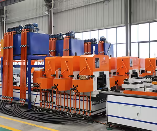
Some photovoltaic components can be punched after they are formed.
This allows the tooling to reference the finished three-dimensional section more directly.
However, it introduces other challenges.
The punch fixture must support the profile without crushing it.
Tool access may be limited by:
- flanges,
- lips,
- deep channels,
- and nearby features.
The best solution depends on the product.
Pre-punching is not automatically better because it is easier.
Post-punching is not automatically better because it references the final section.
The drawings and production volume should determine the sequence.
El punzonado de orificios laterales requiere un posicionamiento de perfil estable
Some brackets contain holes on more than one surface.
For example, a formed C-channel may require:
- web holes,
- flange holes,
- or side connection features.
When punching a formed profile, the machine needs to establish a repeatable three-dimensional position.
A small variation in:
- apertura de canal,
- angul bridului,
- girar,
- or support position
can change where the side punch contacts the profile.
This means forming accuracy and punching accuracy become directly connected.
An unstable upstream profile makes accurate multi-face punching more difficult.
Los componentes del conector necesitan una estrategia de perforación diferente
Not every photovoltaic support component is a long rail.
Mounting structures also use smaller:
- conectores,
- brackets,
- plates,
- and joining components.
These parts may require punching, cutting, and bending within a shorter production cycle.
JBLDIE’s photovoltaic bracket equipment portfolio includes connector-processing equipment in addition to long-profile forming systems. Its broader Máquina formadora de soportes para sistemas solares fotovoltaicos category includes both C/U profile equipment and connector-related machinery.
Long profiles and small components should therefore not always share the same production strategy.
Separating these processes can improve line balance when their cycle requirements are very different.
La sincronización de cortes afecta la posición del orificio final
Even if every hole is correctly positioned relative to the material, a finished bracket can still fail its drawing if the cutter separates the profile at the wrong position.
Consider a profile requiring:
50 mm from first hole to leading end
50 mm from last hole to trailing end
Hole punching and cutting now share the same dimensional chain.
If the cutter drifts by several millimeters, the hole pattern appears shifted relative to the finished part.
For this reason, end distances should be measured after cutting.
The troubleshooting process should distinguish between:
- incorrect punching,
- incorrect feeding,
- and incorrect cutting.
Se debe coordinar el codificador y la referencia de corte
Some lines use separate positioning information for punching and cutting.
Others use shared material-position data.
Whichever architecture is selected, the two systems need a consistent dimensional reference.
Otherwise, the hole pattern can remain stable while finished end distance varies.
Commissioning should therefore include several products with known:
- first-hole position,
- last-hole position,
- overall length,
- and cut-end allowance.
This tests whether punching and cutting operate as one coordinated production system.
Prevención de errores acumulativos en los agujeros
A practical control strategy can include several layers.
Verificar el material entrante
Check width, thickness, grade, and strip condition.
Estabilizar la Sección de Entrada
Avoid excessive upstream tension or uncontrolled strip movement.
Ajuste correctamente la presión del alimentador
Prevent slip without marking or deforming the strip.
Verificar el movimiento del servo
Compare programmed movement against actual finished dimensions.
Utilice comentarios de posición
Monitor material movement using appropriate encoder or measuring systems.
Condición de las herramientas de control
Prevent punch wear from changing hole dimensions.
Inspeccione la posición de largo alcance
Measure first-to-last-hole relationships, not only neighboring pitch.
Corte de coordenadas
Check hole pattern against finished cut ends.
Mida después de formar
Confirm the final bracket rather than only the flat strip.
This multi-stage approach is more reliable than attempting to solve every problem through servo calibration.
Una práctica tabla de solución de problemas de precisión de agujeros
| Symptom | Posible causa | First Check |
|---|---|---|
| Every hole shifted equally | Incorrect datum or starting position | Product zero/reference |
| Pitch varies randomly | Strip slip or feeder instability | Servo feeder and tension |
| Error increases along profile | Cumulative feed error | Long-range feed measurement |
| Holes shift sideways | Strip tracking | Guides and centerline |
| Hole size changes | Punch/die wear | Condición de herramientas |
| Burr increases | Clearance or tool wear | Punch and die |
| Slot distorted after forming | Too close to bend | Inspección de perfil terminado |
| First hole correct, last hole wrong | Acumulación de piensos | Encoder/reference logic |
| Hole pattern correct, end distance wrong | Cutting error | Cutter synchronization |
| Side holes vary | Profile position unstable | Forming and fixture |
| Error starts after coil change | Material/feeding condition | New coil specification |
Cómo solucionar problemas de errores acumulativos
When the last holes of a profile drift but the first hole remains correct, do not immediately adjust the die.
The die determines hole shape.
The problem is more likely related to material positioning.
Begin by producing several parts using the same program.
Measure the error at several locations:
- 500 mm,
- 1,000 mm,
- 2,000 mm,
- 4,000 mm,
- and final position.
If error increases consistently with length, investigate:
- servo calibration,
- measuring-wheel condition,
- deslizador de alimentación,
- encoder feedback,
- and control-reference logic.
If the error appears randomly rather than progressively, inspect material movement and mechanical stability.
La repetibilidad y la precisión no son lo mismo
A machine can be repeatable but inaccurate.
For example, every finished profile may place the first slot exactly 3 mm away from the intended position.
That is a calibration or reference issue.
A machine can also be accurate on average but poorly repeatable.
One profile may be +2 mm, the next -2 mm, and the next +1 mm.
That suggests process instability.
Equipment acceptance should therefore evaluate both:
precisión
How close the mean result is to the target.
y
repetibilidad
How consistently multiple parts reproduce the same result.
A single perfect sample cannot demonstrate repeatability.
Se deben medir varios perfiles consecutivos
During FAT or commissioning, do not inspect only one bracket.
Produce several consecutive finished components.
Medida:
- first-hole position,
- selected internal pitches,
- final-hole position,
- end distance,
- longitud de corte,
- posición transversal,
- and relevant profile dimensions.
If all parts show nearly the same deviation, calibration may be needed.
If deviations vary significantly between parts, process stability should be investigated.
This distinction saves time during troubleshooting.
FAT debería utilizar el patrón de agujero real
A punching machine can look impressive when repeatedly punching one simple hole.
That test provides limited information if the buyer’s actual product contains:
- several long slots,
- multiple hole diameters,
- side holes,
- and different spacing.
A meaningful Factory Acceptance Test should use a representative product drawing.
Buyers should provide one of the more demanding patterns rather than the easiest one.
The test should verify:
- punching sequence,
- material feeding,
- hole quality,
- cumulative position,
- production cycle,
- and finished-part repeatability.
Qué deben preguntar los compradores durante FAT
Las preguntas útiles incluyen:
- What is the material grade used during the test?
- Is the thickness representative of normal production?
- Are actual slots and hole groups being punched?
- How is the first material position established?
- How is cumulative error monitored?
- What device measures actual material movement?
- How many consecutive profiles will be inspected?
- How is hole position measured?
- How is cut-end position synchronized?
- What happens after a product recipe change?
These questions provide more useful information than watching the machine complete a short demonstration cycle.
Tres, seis o nueve estaciones: comience con el dibujo
PV bracket punching equipment is often compared by the number of stations.
A better selection method begins with the hole matrix.
List every required feature:
| Característica | Producto A | Producto B | Producto C |
|---|---|---|---|
| Round web hole | ✓ | ✓ | ✓ |
| Long web slot | ✓ | ✓ | ✓ |
| Side hole | ✓ | ✓ | |
| Large connector hole | ✓ | ||
| Alternative slot | ✓ | ✓ | |
| Special project feature | ✓ |
Then determine which tools need to remain installed simultaneously.
A three-station system may be enough for the first product family.
More stations become useful as the feature matrix expands.
The machine configuration should follow production needs rather than the idea that the largest station count is automatically the most advanced.
Más estaciones pueden mejorar la flexibilidad de cambio
The strongest reason for additional stations is often not raw punching speed.
It can be tooling availability.
If several dies remain mounted on separate stations, the machine may switch between products through:
- program selection,
- feeding changes,
- station activation,
- and limited mechanical adjustment
rather than removing and reinstalling dies every time.
This becomes valuable for factories serving multiple solar projects with shorter production batches.
The real benefit should therefore be measured through:
last qualified Product A → first qualified Product B
not simply by counting hydraulic cylinders.
El crecimiento actual del mercado fotovoltaico aumenta el valor de la flexibilidad
IEA PVPS reported that global PV capacity approached 3 TW by the end of 2025, while deployment continued spreading across a wider number of national markets.
This does not mean every bracket manufacturer automatically needs maximum equipment flexibility.
Dedicated lines can remain highly efficient for stable high-volume products.
However, manufacturers supplying several projects or export markets may need to manage more:
- profile types,
- connection patterns,
- dimensiuni de sloturi,
- finished lengths,
- and material specifications.
For these factories, programmable punching and repeatable changeover become strategically more important than maximum station count alone.
Precisión de perforación y protección de superficies galvanizadas
Many photovoltaic support profiles use galvanized steel.
Punching breaks through the coated sheet and creates a new cut edge.
At the same time, feeding and clamping can mark the broad coated surface if they are not controlled properly.
The U.S. Department of Energy notes that steel and other metal components in PV racking systems can be exposed to corrosion and that material combinations and protective systems need to be considered carefully in harsh environments.
From a manufacturing perspective, the punching line should therefore avoid unnecessary coating damage around areas unrelated to the intended cut.
Verificar:
- feeder rollers,
- clamps,
- guías,
- support tables,
- scrap,
- and finished-product handling.
Punching accuracy and surface quality should be inspected together.
La eliminación de desechos puede afectar la confiabilidad
Every punching operation produces material that needs to leave the tool safely.
Slugs and scrap that remain around the die can create:
- tool jams,
- marcas de superficie,
- double punching,
- sensor alarms,
- or tooling damage.
High-hole-density PV profiles generate more scrap over the same profile length.
Scrap management should therefore be considered during equipment selection.
Pregunta:
- Where do slugs go?
- How are they discharged?
- Can scrap accumulate inside the machine?
- Is the area easy to clean?
- Can sensors detect an abnormal tool condition?
A reliable punching system needs an equally reliable waste path.
El mantenimiento de la herramienta debe basarse en la calidad del producto
Punches and dies are wearing components.
Maintenance should not wait until a tool breaks completely.
Finished parts often show early signs of deterioration.
Useful indicators include:
- increasing burr,
- changing slot dimensions,
- rough edges,
- greater punching noise,
- rising load,
- incomplete slug release,
- or more frequent jams.
Production teams can record tool cycles and inspection results.
This helps connect preventive maintenance with actual component quality.
Gestión de recetas para múltiples soportes fotovoltaicos
A programmable punching system can store different product recipes.
A recipe may contain:
- first-hole location,
- hole sequence,
- pitch,
- active stations,
- longitud de corte,
- product quantity,
- and other production settings.
This can reduce manual re-entry when repeat products return.
However, a stored recipe should not automatically be trusted after:
- reposición de herramientas,
- feeder maintenance,
- encoder change,
- material change,
- or major machine adjustment.
A first-piece check remains necessary.
Digital repeatability depends on mechanical repeatability.
La trazabilidad puede ayudar a diagnosticar problemas de agujeros
Factories serving demanding projects may benefit from connecting production records with material and machine information.
A useful production record can contain:
- numărul coilului,
- grado material,
- grosor,
- product recipe,
- punching-tool set,
- production date,
- dimensional inspection,
- and machine alarms.
Suppose cumulative hole error begins during one shift.
The records can help determine whether the issue coincided with:
- a new coil,
- tool maintenance,
- recipe change,
- feeder adjustment,
- or another event.
Data becomes useful when it supports troubleshooting rather than simply increasing the number of values displayed on an HMI.
Cómo evaluar una máquina perforadora de soportes fotovoltaicos
Before equipment selection, buyers should prepare complete product drawings.
Then ask the supplier to explain the production process around those drawings.
Las preguntas importantes incluyen:
- How many unique hole types are required?
- Which holes can be punched simultaneously?
- Which stations remain installed during changeover?
- How is material position measured?
- How is cumulative feed error controlled?
- How is lateral strip movement controlled?
- What material grade is included in the machine calculation?
- How does punching force change with stronger steel?
- How are slots and round holes inspected?
- How is punching coordinated with cutting?
- How is final hole-to-bend position verified?
- ¿Cómo se elimina la chatarra?
- How are tools maintained?
- What representative product will be used during FAT?
The quality of these answers is more important than a single advertised precision figure.
¿qué información se debe proporcionar antes de la configuración de la máquina?
A complete technical package should include:
Material
Proporcionar:
- grado de acero,
- yield strength where relevant,
- grosor,
- ancho de tira,
- recubrimiento,
- coil size.
Dibujo de agujeros
Proporcionar:
- round-hole diameters,
- dimensiuni de sloturi,
- hole groups,
- longitudinal positions,
- transverse positions,
- side holes,
- tolerances.
Perfil terminado
Proporcionar:
- C/U/Z profile geometry,
- curve,
- lips,
- finished width,
- finished length.
Producción
Proporcionar:
- annual volume,
- common batch size,
- changeover frequency,
- required cycle time,
- expected product mix.
Calidad
Define:
- local pitch tolerance,
- cumulative positioning requirement,
- end distance,
- hole size,
- burr requirement,
- and surface expectations.
This allows the punching system to be engineered around actual production instead of a generic station count.
Una lista de verificación práctica de aceptación del comprador
Before approving a PV bracket punching machine, verify:
Material Feeding
The strip moves consistently without visible slip or uncontrolled lateral movement.
Hole Quality
Round holes and slots meet the required shape and edge condition.
Campo local
Adjacent features remain within the agreed requirement.
Posición acumulada
Long-range hole location remains stable.
Posición transversal
Features remain correctly centered relative to the reference datum.
Finished Profile Position
Punched features remain correct after roll forming.
Distancia final
The cutter separates the profile at the intended position.
Repetibilidad
Several consecutive products show consistent results.
Cambio
Stored recipes and tooling changes reproduce the next product correctly.
Calidad de la superficie
Feeders, guides, and tooling do not create unnecessary coating damage.
Scrap Removal
Punching waste leaves the tool reliably.
Fault Diagnostics
Operators can identify feeder, punch, sensor, and positioning errors clearly.
Conclusión
A Perforadora de soportes fotovoltaicos should be evaluated as a complete positioning and processing system rather than simply a hydraulic press with several dies.
Accurate holes depend on the relationship between servo feeding, strip tracking, material tension, encoder feedback, tooling condition, punching sequence, material properties, roll forming, and final cutting.
For long photovoltaic support profiles, cumulative error deserves particular attention.
A machine may produce acceptable local hole pitch while still allowing the final holes to drift relative to the beginning of the profile. Buyers should therefore measure both short-range and long-range dimensions during machine acceptance.
The number of punching stations should also be selected from the actual product matrix. Three, six, or nine stations only create value when the installed tools correspond with the bracket family’s real hole patterns and reduce practical changeover work.
As PV deployment continues expanding into more markets, manufacturers serving several projects may increasingly benefit from programmable feeding, flexible station configuration, stored recipes, repeatable changeover, and stronger production traceability.
The best equipment selection begins with the finished bracket drawing—not with a machine specification sheet.
Preguntas frecuentes
¿qué es una punzonadora de soportes fotovoltaicos?
A PV bracket punching machine is equipment used to create round holes, slots, connector openings, and other features in photovoltaic mounting components. It can work with flat strip, formed profiles, or integrated roll forming production lines.
¿qué causa el error acumulativo de posición de huecos en los brackets
Possible causes include servo-feed calibration, strip slip, encoder error, unstable feeder pressure, upstream tension, mechanical wear, or control-reference problems. Long-range measurements are needed to distinguish cumulative error from local pitch variation.
¿es mejor una punzonadora de nueve estaciones que una de tres estaciones?
Not automatically. The correct station count depends on the number of hole types, processing surfaces, product variations, and changeover requirements. A simpler product may not benefit from unused stations.
¿deben perforarse los orificios de los soportes fotovoltaicos antes o después del perfilado?
Both approaches are possible. Pre-punching provides easier tool access, while post-punching can reference finished profile geometry more directly. The correct sequence depends on hole location, profile shape, tolerance, volume, and tooling access.
¿qué deberían probar los compradores durante la máquina perforadora de soportes fotovoltaicos FAT?
Buyers should test representative material and actual hole patterns while checking hole dimensions, local pitch, cumulative position, transverse location, cut-end distance, production cycle, repeatability, and changeover performance.
¿necesita configurar el equipo de perforación de soportes fotovoltaicos?
The punching system should be developed from your actual bracket profile, material grade, thickness, round holes, slots, side features, cumulative positioning requirements, production volume, and changeover needs. Contact JBLDIE to discuss your photovoltaic bracket drawings and punching requirements.
 Spanish
  English
  Arabic
  Russian
  French