
7 Checks Before Adding an Automatic Punching Machine to a PV Line
Table of Contents
An automatic punching machine can improve the speed, repeatability and process continuity of a photovoltaic bracket production line. However, adding punching equipment does not automatically increase qualified output. If the press force, feeding system, tooling layout or control logic does not match the actual bracket drawings, punching can become the main bottleneck of the entire line.
Solar mounting components often contain repeated round holes, elongated slots, connector holes, notches and cut-off features. Their positions affect assembly, alignment and compatibility with other parts of the mounting structure. The punching process must therefore be evaluated as part of the complete production system rather than as an independent machine specification.
Before adding an automatic punching machine to a PV production line, manufacturers should check:
- Finished-part drawings and hole patterns
- Raw-material strength and punching force
- Feeding and positioning accuracy
- Tooling arrangement and changeover requirements
- Real cycle time and line synchronization
- Inline integration and factory layout
- Safety, maintenance and acceptance testing
The most suitable machine is the one that produces every agreed hole and formed feature within tolerance while remaining synchronized with feeding, roll forming, cutting and finished-product handling.
How Automatic Punching Supports PV Bracket Production
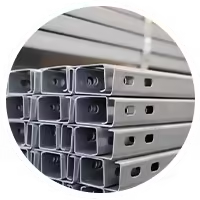
An automatic punching machine uses a controlled feeding and press system to create holes, slots, notches or formed features in metal strip or prepared blanks. In a photovoltaic production line, it may process structural rails, mounting channels, connector plates, support posts and other components.
Depending on the finished product, the system may combine:
- Coil feeding
- Strip leveling
- Servo positioning
- Multi-station punching
- Notching
- Embossing
- Part forming
- Measuring
- Cutting
- Counting
- Discharge and stacking
Jinbolida’s Solar Photovoltaic Rack Punching Equipment range includes three-, six- and nine-station hydraulic punching equipment, connector punching machines and related systems for photovoltaic components.
Automation is most valuable when it removes repeated manual positioning and connects several operations under one control system. The objective is not simply to increase strokes per minute. It is to produce correctly positioned features without cumulative error, excessive burrs, surface damage or repeated secondary handling.
Check 1: Confirm Every Hole Pattern and Finished-Part Drawing
The first check should focus on the finished products rather than the advertised capacity of the punching machine.
Manufacturers should prepare complete drawings for every product that may pass through the system. Drawings should clearly identify:
- Overall component dimensions
- Material thickness
- Hole shape
- Hole diameter
- Slot length and width
- Hole-to-hole distance
- Hole-to-edge distance
- Number of repeated features
- Part-forming operations
- Cut length
- Required tolerances
- Reference datum
A general statement such as “the line needs round holes and slots” is insufficient for tooling design. Two products can contain the same type of slot but require different station arrangements because their spacing, orientation or surrounding bends are different.
Create a Hole-Pattern Matrix
A hole-pattern matrix makes it easier to determine which products can share punches and dies.
| Product feature | Product A | Product B | Product C | Tooling implication |
|---|---|---|---|---|
| Round hole | 12 mm | 12 mm | 14 mm | A and B may share tooling |
| Long slot | 14 × 30 mm | 14 × 40 mm | None | Separate slot punches required |
| Hole pitch | 50 mm | 100 mm | Variable | Servo feeding or programmable sequence |
| Side notch | No | Yes | Yes | Additional station may be needed |
| Embossed feature | No | No | Yes | Forming station and force check required |
| Part length | Fixed | Multiple | Multiple | Programmable cutting required |
This comparison helps determine the number of stations, die arrangement and control recipes.
Define the Datum System
Hole-position accuracy must be measured from an agreed reference. Possible references include the leading edge, centerline, profile edge or another punched feature.
Without a consistent datum, inspection results from the equipment manufacturer and product factory may not be comparable.
For photovoltaic rails and channels, hole positions may also need to correspond with the final formed section. The tooling engineer must understand whether dimensions are specified on the flat strip or on the completed profile.
Check 2: Match Punching Force to the Material
Required punching force depends on more than material thickness. It is influenced by material shear strength, total cutting perimeter, number of holes punched at the same time and tooling clearance.
Important material information includes:
- Material grade
- Yield strength
- Tensile or shear strength
- Minimum and maximum thickness
- Strip width
- Surface coating
- Coil dimensions
- Expected hardness variation
An automatic punching machine designed for thin, low-strength strip may not provide stable results when processing thicker or higher-strength steel.
Consider Simultaneous Punching
A multi-station system may punch several features during the same cycle. The required force should be calculated for the maximum combined cutting perimeter, not only for one individual hole.
Force margin is also necessary for:
- Material-property variation
- Tool wear
- Formed or embossed features
- Stripping force
- Off-center loading
- Production at the maximum specified thickness
However, selecting an unnecessarily large press can increase energy demand, floor-space requirements and tooling complexity. Equipment sizing should be based on the most demanding agreed product rather than a broad safety guess.
Tool Clearance Affects Quality
Punch-to-die clearance influences force, burr height, edge condition and tool life. Incorrect clearance may cause:
- Heavy burrs
- Secondary tearing
- Distorted holes
- Slug pulling
- Rapid punch wear
- Cracking near the hole
- Increased press load
The correct clearance depends on material type, strength and thickness. If one line processes a broad thickness range, the supplier should explain how tooling clearance will be managed.
Check 3: Verify Feeding and Positioning Accuracy
A powerful press cannot produce accurate hole locations if the material is not positioned consistently.
Servo feeding is commonly used because it can move the strip according to programmed distances. The feeder may receive commands from a PLC or CNC control system for each product recipe.
Positioning performance depends on:
- Encoder resolution
- Servo response
- Roller grip
- Strip straightness
- Leveling quality
- Material surface
- Guide alignment
- Acceleration settings
- Control compensation
- Calibration condition
Avoid Cumulative Error
Suppose a long photovoltaic rail contains dozens of repeated slots. If every feed movement contains a small uncorrected error, the final hole may be significantly displaced from its intended position.
A system can reduce this risk through:
- Encoder feedback
- Registration marks
- Reference-hole detection
- Periodic position correction
- Non-cumulative programming
- Cutting from a fixed datum
- In-process measurement
The supplier should explain whether quoted accuracy applies to one feed movement, one individual feature or the complete finished product.
Leveling Comes Before Accurate Feeding
Coil curvature can reduce contact between the strip and feeding rollers. It may also cause the strip to lift or move sideways during positioning.
A suitable leveling unit should prepare the material before it enters the feeder and punching area. The adjustment range should match the minimum and maximum material thickness.
Test Short and Long Products
Positioning should be verified on both short and long components. Short pieces reveal rapid acceleration and cutting coordination, while long pieces help expose cumulative error and strip-tracking problems.
Check 4: Evaluate Tooling Stations and Changeovers
The number of punching stations should correspond to the product family. More stations can improve flexibility, but they also increase machine length, tooling management and maintenance requirements.
Jinbolida offers equipment such as the Nine-Station Punch Machine for production requiring multiple punching operations and programmable feeding.
Single-Station Punching
A single station may be appropriate when:
- One feature dominates production
- Hole patterns are simple
- Batch sizes are large
- Tool changes are infrequent
- The line produces a limited product range
Multi-Station Punching
Multiple stations may support:
- Different hole diameters
- Round holes and slots
- Notches
- Embossing
- Separate connector features
- Several product recipes
- Reduced die-change frequency
The control system should activate only the stations required for the selected product.
Examine Changeover Procedures
A changeover may involve more than loading a new recipe. Operators may need to:
- Replace punches and dies
- Adjust guides
- Change strip width settings
- Reset feeder positions
- Adjust press stroke
- Replace cutting tools
- Clear old production data
- Inspect the first new part
The supplier should provide an expected changeover time and demonstrate the procedure during acceptance testing.
Plan Tool Storage and Identification
Punching tools should be clearly identified by product and feature. A practical tooling system may include:
- Tool numbers
- Product compatibility records
- Material and thickness limits
- Recommended clearance
- Maintenance history
- Sharpening records
- Storage locations
- Replacement-part drawings
Tooling management is especially important for factories producing multiple photovoltaic bracket specifications.
Check 5: Calculate Real Cycle Time
Press speed alone does not determine production capacity. The entire punching cycle includes positioning, clamping, punching, return movement, scrap removal and material transfer.
Real cycle time may include:
- Feeder acceleration
- Material positioning
- Position confirmation
- Press movement
- Punch penetration
- Tool return
- Slug removal
- Next feed movement
- Cutting or part discharge
A system with a fast press but slow positioning may produce fewer qualified parts than a balanced system with moderate press speed.
Compare Strokes with Finished Output
Suppliers may describe capacity using strokes per minute. This number does not show how many finished components are produced because one component may require several strokes.
A more useful capacity measure is:
- Qualified components per minute
- Qualified components per hour
- Qualified components per shift
- Completed profile length per shift
- Rejection rate under continuous production
For connector components, Jinbolida’s Solar Photovoltaic Bracket Connector Punching Machine integrates punching, cutting and forming within one automated system. Its published product page can be used as a reference when evaluating whether several connector operations should be combined.
Use the Most Complex Product for Capacity Testing
A simple product with one hole cannot represent the capacity of a product containing multiple slots, notches and formed features.
The acceptance test should include:
- A high-volume standard product
- The product with the densest hole pattern
- The thickest agreed material
- The longest product
- At least one changeover
- Continuous operation under realistic settings
Check 6: Decide How the Machine Will Integrate with the PV Line
An automatic punching machine can operate inline with the roll former or as a separate production cell. The correct choice depends on product flow, changeover frequency and factory capacity.
The article Solar Bracket Punching Machine: Inline vs Separate Systems provides a direct comparison of these two arrangements.
| Evaluation factor | Inline punching | Separate punching |
|---|---|---|
| Material handling | Reduced between operations | Additional transfer required |
| Process flow | Connected with forming and cutting | Independent scheduling |
| Line balance | Punching can limit the full line | Each machine can run separately |
| Product tracking | Easier within one control system | Requires batch identification |
| Changeovers | Several units may need adjustment | Punching can change independently |
| Floor-space use | Long connected layout | Separate work cells and storage |
| Flexibility | Effective for repeated products | Useful for varied short batches |
| Work-in-process | Usually lower | Intermediate inventory required |
Inline Automatic Punching Machine
Inline punching is suitable when the same coil passes directly from leveling and punching into a Solar Photovoltaic Bracket Forming Machine.
Advantages include:
- Reduced material handling
- Consistent product identification
- Fewer intermediate storage areas
- Coordinated feeding and cutting
- Easier production counting
- Potentially lower work-in-process inventory
The main limitation is line balance. If punching stops, forming and cutting may also stop.
Separate Automatic Punching Machine
Separate equipment can be useful when:
- Several lines share punching capacity
- Hole patterns change frequently
- Products are produced from blanks
- Forming and punching have different batch schedules
- Existing roll forming lines cannot accept inline equipment
The factory must plan safe transport, storage and identification of partially processed material.
Check Control-System Communication
An integrated system may need to exchange:
- Start and stop commands
- Speed references
- Product recipes
- Batch quantities
- Feeder positions
- Punch-complete signals
- Cutting commands
- Alarm status
- Safety status
The interface responsibility should be clearly assigned. When equipment comes from different suppliers, signal lists, communication protocols and commissioning responsibilities must be confirmed before installation.
Check 7: Review Safety, Maintenance and Acceptance Testing
Automatic punching contains high-force tooling and repeated mechanical or hydraulic movement. Safety must be included in the original system design.
The OSHA machine-guarding guidance identifies hazards associated with moving machine parts and the need for appropriate safeguards. OSHA also publishes requirements addressing mechanical power presses, although the exact regulations applicable to a factory depend on its location, machine type and operating conditions.
A machine-specific risk assessment should consider:
- Punching and die area
- Feeding rollers
- Moving strip
- Coil handling
- Hydraulic pressure
- Electrical systems
- Ejected slugs
- Cutting station
- Automatic discharge
- Setup and maintenance access
Essential Safety Functions
Depending on the machine configuration, safety measures may include:
- Fixed guards
- Interlocked access doors
- Light curtains
- Emergency stops
- Two-hand controls for setup modes
- Safety relays or controllers
- Pressure monitoring
- Overload protection
- Guarded scrap discharge
- Lockout points
- Controlled manual-jog operation
Production speed should never be increased by bypassing safety devices.
Maintenance Access
A machine may operate automatically but still requires manual inspection, lubrication, cleaning and tooling replacement.
Maintenance planning should cover:
- Punch and die wear
- Tool sharpening
- Feeder roller condition
- Guide alignment
- Hydraulic oil and filters
- Lubrication
- Sensors and encoders
- Electrical cabinets
- Scrap chutes
- Safety interlocks
The line layout should provide enough clearance to remove tooling and service major components.
Factory Acceptance Test
Before shipment, the automatic punching machine should be tested with the agreed material and representative products.
The FAT should verify:
- Material loading
- Leveling
- Feeding accuracy
- Every required hole and slot
- Hole-position tolerance
- Burr condition
- Product dimensions
- Cutting accuracy
- Changeover time
- Continuous output
- Scrap removal
- Alarm handling
- Safety functions
- Recipe storage
- Data recording
The results should identify the drawing, material grade, thickness, tool set and measurement method used.
Automatic Punching Machine Selection Checklist
Before finalizing the configuration, confirm the following information.
| Selection item | Information required | Why it matters |
|---|---|---|
| Product range | Drawings for every part | Determines tooling and station count |
| Material | Grade, strength and thickness | Determines force and clearance |
| Hole patterns | Sizes, shapes and spacing | Determines dies and feeding program |
| Tolerances | Position, size and cut length | Defines equipment accuracy |
| Production target | Parts per shift and batch size | Determines required cycle time |
| Integration | Inline or separate | Affects layout and controls |
| Changeovers | Frequency and product combinations | Determines tooling strategy |
| Utilities | Voltage, hydraulic and pneumatic needs | Supports installation planning |
| Safety | Factory and regional requirements | Determines guards and controls |
| Acceptance | Materials, products and test duration | Provides measurable FAT criteria |
Information to Send the Equipment Manufacturer
A detailed technical package helps the supplier recommend an appropriate machine instead of estimating from a general product description.
Include:
- Finished-part drawings
- Flat-strip or blank drawings
- Raw-material specifications
- Minimum and maximum thickness
- Coil dimensions
- Hole and slot details
- Required tolerances
- Product-length range
- Annual volume
- Batch quantities
- Changeover frequency
- Existing production-line layout
- Roll forming speed
- Cutting method
- Required automation
- Factory voltage and frequency
- Preferred feeding direction
- Safety requirements
- FAT standards
Manufacturers planning a complete line should ensure the punching proposal is reviewed together with the roll forming, cutting and receiving systems.
Common Integration Mistakes
Selecting by Press Tonnage Alone
Sufficient force is essential, but it does not guarantee accurate feeding, suitable tooling or efficient output.
Ignoring Hole Density
Closely spaced holes and slots may reduce line speed even when the roll former can operate faster.
Testing Only One Feature
Every hole, slot, notch and formed detail should be tested, especially on the most complex product.
Treating the Feeder as a Minor Component
The feeder determines whether the tool acts at the intended location. Positioning accuracy should be tested across the full product length.
Underestimating Scrap Removal
Slugs and strip scrap can block tooling, contaminate sensors and interrupt production if discharge is not reliable.
Leaving Interface Responsibility Undefined
When the punching machine and roll forming line come from different systems, unclear control responsibilities can delay commissioning.
Conclusion
Adding an automatic punching machine to a photovoltaic production line can improve repeatability and reduce manual positioning, but only when the machine matches the finished components, materials and complete production cycle.
The seven essential checks are product drawings, punching force, feeding accuracy, tooling arrangement, real cycle time, line integration, and safety with acceptance testing. Each item should be supported by measurable technical information rather than general claims about speed or automation.
Jinbolida provides photovoltaic rack punching equipment, photovoltaic bracket forming machines and customized automated production systems. Manufacturers can submit drawings, material data, hole patterns, output requirements and factory-layout information through the Jinbolida contact page for a line-specific evaluation.
FAQ
What does an automatic punching machine do in a PV bracket line?
It positions metal strip or prepared blanks and creates programmed holes, slots, notches or formed features used in solar mounting components. The machine may also integrate cutting and part forming. Its performance depends on feeding accuracy, tooling design, material strength and synchronization with the rest of the production line.
How much punching force does a photovoltaic bracket require?
Required force depends on the material’s shear strength, thickness, total cutting perimeter and number of features punched simultaneously. Formed or embossed details and stripping force must also be considered. The supplier should calculate force using the most demanding agreed product rather than relying on one general tonnage estimate.
Is inline punching always better than separate punching?
No. Inline punching reduces handling and connects production, but it can limit the full line when punching cycles are slower than forming. Separate equipment provides independent scheduling and may suit varied batches, although it requires additional handling and tracking. The correct choice depends on product mix, volume and factory layout.
How can cumulative hole-position error be prevented?
A controlled servo feeder, calibrated encoder, stable leveling and clear product datum help prevent cumulative error. Some systems also use reference marks or periodic position correction. Accuracy should be tested across the complete finished product, because verifying one short feed movement does not prove long-length positioning performance.
What should be checked during an automatic punching machine FAT?
The FAT should use agreed production material and include every required feature. Check hole size and location, burrs, feeding accuracy, cutting, changeovers, continuous output, scrap removal, recipes, alarms and safety functions. Record the drawing, material, tool set, inspection method and acceptance result for each tested product.
 English
  Arabic
  Russian
  Spanish
  French