
Automatic Roll Forming Line: Punching to Cutting
Table of Contents
Introduction
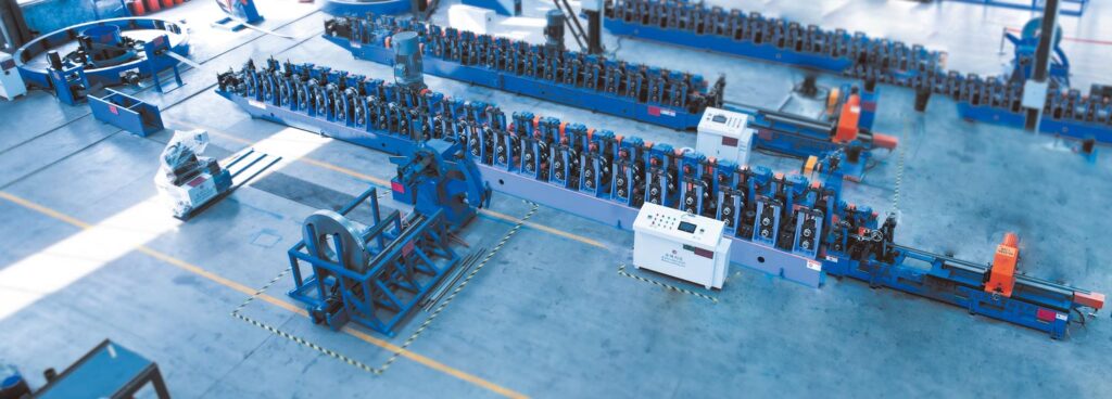
A roll forming machine can continuously shape metal strip into a specified profile, but many finished components require much more than forming alone. Solar mounting channels need slots and holes. Structural profiles may require repeated connection patterns. Construction components need controlled lengths. Other products must be automatically transferred, counted, stacked, or prepared for downstream processing.
An automatic roll forming line connects these operations into one coordinated production system. Depending on the finished product, the line can integrate coil loading, decoiling, leveling, servo feeding, punching, roll forming, measuring, cutting, unloading, stacking, and production-data collection.
The main advantage of automation is not simply replacing manual work. A well-designed line coordinates each processing stage so that material moves through the correct sequence with fewer unnecessary stops and transfers. However, the speed of the roll former alone does not determine the capacity of the complete line. Punching cycles, feeder acceleration, cutting time, material changeover, unloading, and even scrap removal can become production bottlenecks.
For this reason, an automatic roll forming line should be engineered backward from the finished product and its required manufacturing process.
What Is an Automatic Roll Forming Line?
An automatic roll forming line is an integrated production system that converts metal coil into finished profiles while coordinating several processing operations through mechanical equipment and centralized controls.
A basic line may consist of:
decoiling → leveling → feeding → punching → roll forming → cutting → receiving
More advanced configurations can add:
- automatic coil loading,
- coil storage,
- servo-controlled feeding,
- multiple punching stations,
- marking,
- online dimensional monitoring,
- flying cutting,
- automatic unloading,
- turning,
- robotic transfer,
- stacking,
- production counting,
- recipe management,
- and manufacturing-data recording.
The correct configuration depends on the profile.
A C-channel with no holes may require relatively simple forming and cutting. A photovoltaic support profile with several slot patterns may require multiple punching operations and programmable feeding. A structural component with several profile sizes may place greater emphasis on automatic changeover.
JBLDIE’s forming machine solutions integrate feeding, punching, forming, cutting, and related automation according to finished-profile and production requirements.
Automation Should Start With the Finished Product
One of the most important principles in automated line design is to begin with the product drawing rather than the available machines.
The drawing determines:
- cross-sectional geometry,
- material,
- thickness,
- strip width,
- hole patterns,
- slots,
- embossments,
- cut length,
- tolerances,
- surface requirements,
- and downstream assembly features.
These product characteristics determine the process sequence.
For example, a profile containing several holes near bends may require careful consideration of whether punching should occur before or after forming.
A long profile with multiple programmable hole patterns may benefit from servo feeding.
A product requiring several lengths can use programmable cutting without changing the roll tooling.
Automation should therefore be built around the manufacturing logic of the component rather than adding machines together simply because they can communicate with a PLC.
Typical Automatic Roll Forming Line Process
A complete automatic line can be divided into several connected production stages.
| Production Stage | Main Function | Important Control |
|---|---|---|
| Coil loading | Position raw coil | Weight, width and centerline |
| Decoiling | Release strip | Stable material delivery |
| Leveling | Reduce coil set | Flatness and strip condition |
| Servo feeding | Position material | Feed length and synchronization |
| Punching | Create holes and slots | Position, pattern and cycle time |
| Roll forming | Create profile geometry | Tooling, alignment and roll gap |
| Measuring | Track product position | Encoder and sensor accuracy |
| Cutting | Produce finished length | Timing and profile support |
| Unloading | Remove finished profile | Cycle synchronization |
| Stacking | Organize completed parts | Orientation and handling |
| Data control | Manage recipes and output | Reliable production information |
Not every line needs all of these operations. The system should contain only the processes required by the actual product and production model.
Coil Loading Is the Beginning of Automation
Automation often receives the most attention around punching and forming, but the production process begins before the strip enters the first machine.
Heavy coils need to be positioned safely and accurately at the entry section.
A coil car, loading device, or automated transfer system can help move coils into the correct decoiler position.
The coil should be centered relative to the production line.
If the raw material begins several millimeters or centimeters away from the intended centerline, downstream guides may be forced to correct that error continuously.
This can create:
- lateral strip force,
- edge rubbing,
- guide wear,
- camber,
- or uneven forming.
Good automation therefore begins with stable material positioning rather than trying to correct poor alignment farther downstream.
Decoiling Must Match the Downstream Line
The decoiler holds the coil and releases strip into the production line.
It should supply material without creating uncontrolled tension or lateral movement.
Depending on the line configuration, the decoiler may work with:
- a loop,
- leveler,
- pinch feeder,
- accumulator,
- or servo feed system.
The relationship between these machines matters.
A servo feeder should not be expected to pull a heavy coil directly against excessive decoiler resistance during every positioning cycle.
Likewise, uncontrolled coil release can cause unstable strip loops.
The entry section should create a controlled buffer so downstream precision equipment receives material under repeatable conditions.
Leveling Prepares the Strip for Accurate Processing
Coiled material naturally contains curvature from storage on the coil.
Before punching or precise forming, the strip may need to pass through a leveler.
The leveling section reduces coil set and helps create a more stable condition for downstream processing.
This becomes especially important when punching requires consistent contact between the flat strip and die.
Poor leveling can contribute to:
- unstable feeding,
- inaccurate punching,
- strip movement,
- and inconsistent entry into the forming stands.
Leveling settings should correspond with material thickness and strength.
A line processing several material specifications may therefore require different approved leveling settings for each product family.
Servo Feeding Connects Material Position With the Production Program
Servo feeding is one of the key components in many automatic roll forming lines.
The feeder advances strip according to programmed distances.
This allows the control system to coordinate material position with:
- punching,
- notching,
- embossing,
- marking,
- and certain cutting operations.
Suppose a profile contains several different hole spaces.
Instead of using one fixed mechanical pitch, a servo-controlled sequence can theoretically follow a programmed pattern such as:
feed → punch → feed → punch → longer feed → punch → feed → cut
This makes the line more flexible when different products use different longitudinal feature patterns.
However, programmed distance is not the same as guaranteed physical accuracy.
Feed-roll slip, upstream strip tension, acceleration, material condition, and mechanical wear can influence actual movement.
Finished-product inspection is therefore still necessary.
Punching Is Often the Real Capacity Bottleneck
A roll forming machine may be mechanically capable of moving strip continuously at relatively high speed.
Punching works differently.
Every hole or slot may require a press cycle.
If a finished profile contains many punched features, the punching section can limit how quickly the entire line operates.
Consider two products.
Product A contains four holes.
Product B contains forty holes.
Both may use the same cross-section and roll tooling, but their actual production capacity can be very different because Product B requires many more punching cycles.
When estimating automatic roll forming line capacity, manufacturers should therefore consider:
- number of punching strokes,
- stroke cycle time,
- feeder movement,
- tool configuration,
- scrap discharge,
- product length,
- and hole distribution.
Using only maximum roll forming speed can significantly overestimate real finished output.
Single-Station vs Multi-Station Punching
Punching requirements determine how many tools or stations are appropriate.
A simple product may need only one punching station.
A more complicated component may contain several:
- hole diameters,
- slot shapes,
- connection patterns,
- embossments,
- or different feature groups.
One approach is to place several dies in one larger punching system.
Another is to divide operations between multiple stations.
The correct choice depends on:
- product geometry,
- processing sequence,
- cycle time,
- tooling accessibility,
- maintenance,
- and product variation.
Adding more stations does not automatically increase productivity.
Each additional station also adds synchronization, tooling, maintenance, and control requirements.
The punching architecture should therefore solve the actual product-processing problem.
Pre-Punching Before Roll Forming
Many automatic lines punch the strip while it is still flat.
Pre-punching offers several practical advantages.
The material can be supported on a relatively simple flat die surface.
Punch tooling has easier access.
Scrap can be removed more directly.
Multiple hole patterns can also be coordinated with servo feeding before the strip enters the forming stands.
However, final hole position needs to account for subsequent deformation.
If a punched feature sits close to a bend line, roll forming can alter:
- hole shape,
- local geometry,
- or the relationship between the hole and finished profile.
For this reason, final inspection should be performed after forming rather than accepting hole position based only on flat-strip punching.
When Post-Punching May Be Necessary
Some holes reference the final three-dimensional geometry rather than the original flat strip.
In these cases, punching after partial or complete forming may be more appropriate.
Post-punching introduces different tooling challenges because the formed profile needs support during the press operation.
The die should avoid crushing or distorting the section.
Tool access may also be more restricted.
The choice between pre-punching and post-punching should therefore be made during process engineering, not after the machines have already been selected.
The profile drawing and tolerance requirements should determine the correct sequence.
Roll Forming Is the Continuous Core of the Line
After the required upstream operations, the strip enters the roll forming section.
A sequence of roller stations gradually transforms the flat strip into the finished cross-section.
Each stand performs part of the total deformation.
The process can form:
- C channels,
- U channels,
- Z profiles,
- roofing sections,
- solar mounting profiles,
- structural channels,
- guardrail components,
- and many customized metal sections.
The tooling progression needs to remain stable even when the upstream process operates intermittently.
If punching requires frequent stop-start movement while the roll former is designed around continuous motion, the overall architecture needs to account for that difference.
This is one reason accumulator, servo, or synchronized control strategies become important in more complex lines.
Continuous vs Intermittent Material Movement
Not every automatic roll forming line handles material in exactly the same way.
Some lines operate with largely continuous strip movement.
Others repeatedly stop for punching or cutting.
This difference affects system design.
An intermittent line may follow:
feed → stop → punch → feed → stop → punch → form → stop → cut
A more continuous line may separate intermittent processing from continuous forming using buffering or equipment capable of operating while material moves.
Neither method is universally better.
The selection depends on:
- hole density,
- line speed,
- profile length,
- tooling,
- cutting method,
- product variety,
- and required output.
The most effective line minimizes unnecessary conflict between process stages.
Cutting Is Another Potential Bottleneck
After forming, the continuous profile needs to be separated into finished lengths.
The cutting system must coordinate with the material movement.
Two general strategies are commonly used.
Stop-to-cut
The material pauses while the cut is made.
This can simplify cutting mechanics but interrupts continuous movement.
Flying cut
The cutting equipment moves with the profile while performing the cut.
This allows the main forming process to remain more continuous but requires accurate synchronization between product speed and cutter movement.
The appropriate method depends on production requirements.
A flying cutter is not automatically necessary for every line, while a stop-to-cut system may limit throughput in high-speed applications.
Why the Cut-Off Tool Must Match the Profile
Complex roll formed sections cannot always be cut effectively with a generic flat blade.
The tooling needs to support the finished profile while the cutting force is applied.
If the profile is poorly supported, cutting can create:
- crushed edges,
- flare,
- burrs,
- dimensional change,
- or surface damage.
Automatic production makes cutting repeatability even more important because one poor mechanical condition can affect every part continuously.
The cut-off process should therefore be developed from the finished cross-section in the same way as the roll tooling.
Measuring Finished Length
Automatic cutting depends on knowing where the product is located.
Length measurement may involve:
- encoders,
- measuring wheels,
- servo data,
- sensors,
- or other position-control systems.
The measurement system should reflect actual profile movement.
A measuring wheel that slips against the material can create length variation even if the PLC calculation is correct.
During commissioning, several consecutive parts should therefore be measured physically.
The objective is to verify that:
programmed length = actual finished length
within the required tolerance.
Automatic Unloading Can Become the Hidden Bottleneck
Once a finished profile is cut, it needs to leave the cutting area before the next product arrives.
At moderate production rates, an operator may remove parts manually.
At higher output, manual unloading can become the limiting operation.
If the roll forming and cutting sections produce profiles faster than workers can remove them, the complete line needs to slow down.
Automatic unloading can use:
- conveyors,
- pushers,
- transfer arms,
- robotic devices,
- or other handling systems
depending on product geometry.
The unloading cycle should be included in capacity calculations just like punching and cutting.
Long Profiles Need Controlled Handling
Roll formed products can be several meters long.
Long profiles are more difficult to handle automatically because they may:
- flex,
- rotate,
- interfere with guides,
- scratch against one another,
- or become unstable during transfer.
The handling equipment needs enough support points for the finished profile.
A narrow structural channel and a wide roofing panel, for example, require very different unloading strategies.
Automation should therefore follow product geometry.
A handling system that works well for short punched brackets may be unsuitable for long structural profiles.
Automatic Turning and Orientation
Some downstream processes require the finished profile to arrive in a specific orientation.
A profile may leave the roll forming machine with its open side upward but need to be stacked or assembled with that side downward.
An automatic turning mechanism can rotate the part before stacking or downstream transfer.
This is useful where profiles need to enter:
- welding,
- assembly,
- packaging,
- or palletizing
in a consistent orientation.
However, turning adds another cycle to the line.
The required motion should therefore be coordinated with cutting and unloading so it does not become a new production bottleneck.
Automatic Stacking
Stacking is often the final stage before packaging or downstream processing.
An automatic stacking system can arrange finished profiles according to:
- quantity,
- orientation,
- layer,
- bundle size,
- or downstream handling requirement.
This can reduce repeated manual handling.
However, stacking quality matters.
Poorly aligned stacks can make later bundling or forklift movement more difficult.
Surface-sensitive profiles should also be placed without unnecessary scratching.
The stacking strategy should therefore be defined together with packaging and internal logistics rather than treated as a purely mechanical end-of-line function.
How the PLC Coordinates the Complete Line
The PLC acts as the control coordinator for many automatic production lines.
It can manage signals between:
- decoiler,
- leveler,
- servo feeder,
- punching system,
- roll former,
- cutter,
- conveyor,
- unloading equipment,
- and stacking system.
The control logic needs to know whether each stage is ready before the next movement begins.
For example, material should not advance into a punching tool that has not fully returned.
The cutter should not activate before the profile reaches the correct position.
The next finished part should not enter an unloading zone that remains occupied.
Automation therefore depends heavily on interlocks and sequence logic.
Recipe Management Improves Repeatability
A production line handling multiple products can store product-specific recipes.
Depending on the system, a recipe might include:
- feed lengths,
- punching sequence,
- hole spacing,
- cut length,
- production quantity,
- speed settings,
- and selected automatic functions.
This reduces repeated manual data entry.
However, electronic recipes do not replace mechanical setup.
If another profile requires different roll tooling, punching dies, guides, or cut-off tooling, those components still need to be installed and verified correctly.
Digital control and physical setup must correspond.
Automation Does Not Fix an Unstable Mechanical Process
This principle is particularly important.
A PLC cannot correct a worn roller.
A servo cannot compensate reliably for strip slipping because of poor material control.
More sensors cannot fix an incorrectly aligned roll stand.
Automatic stacking does not improve a profile that already twists after cutting.
The underlying mechanical process needs to be stable before automation creates value.
This is also consistent with the broader direction of smart manufacturing. NIST’s 2026 roadmap for AI and machine learning in smart manufacturing highlights the importance of integrating data, sensing, control systems, autonomous systems, and reliable industrial operation rather than treating digital technologies as isolated functions.
For an automatic roll forming line, good mechanical engineering remains the foundation on which digital control is built.
Sensors Should Solve Defined Problems
Modern production lines can contain many sensors, but more sensors do not automatically mean better production.
A sensor should provide information that supports:
- machine sequencing,
- quality,
- safety,
- troubleshooting,
- maintenance,
- or production planning.
Useful examples include:
- material-presence sensors,
- coil-loop sensors,
- feeder-position feedback,
- punch-position sensors,
- cutter-position sensors,
- product-detection sensors,
- unloading confirmation,
- stack-height detection,
- and safety interlocks.
Every sensor introduces another component that needs correct positioning and maintenance.
The value should therefore justify the additional complexity.
Production Data Can Reveal the Real Bottleneck
Automatic production lines can record information that manual lines often leave undocumented.
Useful data can include:
- finished quantity,
- cycle time,
- machine stops,
- alarm history,
- changeover time,
- punching cycle,
- material use,
- and downtime.
This information helps answer an important question:
Which part of the line actually limits production?
The answer may not be the roll former.
Repeated analysis can reveal that most lost time comes from:
- coil changes,
- punching,
- cut-off delay,
- unloading,
- tooling changes,
- or alarm recovery.
Improvement can then focus on the actual constraint.
How to Calculate Real Automatic Line Capacity
A realistic capacity calculation should consider the entire manufacturing cycle.
Suppose the roll former can theoretically process material at a given line speed.
The finished output may still depend on:
Punching time
How many strokes does each product require?
Feeding time
How far does material move between operations?
Cutting time
Does the line stop to cut?
Unloading time
How quickly can the finished product leave the cutting zone?
Changeover
How often does tooling or material change?
Coil replacement
How much time is lost between coils?
Maintenance and inspection
How frequently does the line need planned interruption?
The practical capacity is determined by the slowest recurring requirement within the complete system.
Automatic Roll Forming Line Bottleneck Table
| Bottleneck | Typical Cause | Possible Engineering Direction |
|---|---|---|
| Coil change | Slow material preparation | Buffer or improved coil handling |
| Feeding | Long movements or strip slip | Motion optimization and material control |
| Punching | Too many press cycles | Multi-station tooling or process review |
| Forming | Unstable profile at higher speed | Tooling and alignment improvement |
| Cutting | Stop-to-cut cycle too slow | Review cutting strategy |
| Unloading | Finished profiles accumulate | Automatic transfer |
| Stacking | Long handling cycle | Stack sequence optimization |
| Changeover | Excessive manual adjustment | Standardized or adjustable tooling |
| Quality inspection | Defects found too late | In-process control |
| Alarm recovery | Poor fault information | Better diagnostics |
Automation improvements should target the bottleneck that actually affects production rather than adding complexity uniformly across every stage.
Quality Control Should Be Integrated Into the Line Strategy
An automatic line can produce unacceptable components automatically just as efficiently as acceptable ones.
Quality control therefore needs to remain part of the process.
Important checks may include:
- material specification,
- strip width,
- hole position,
- profile dimensions,
- bend angles,
- finished length,
- straightness,
- surface condition,
- and repeatability.
Some measurements may remain offline.
Others can potentially be monitored through sensors or machine data depending on the application.
The most important point is to detect process drift before a large batch has been produced.
First-Piece Inspection Still Matters
Automatic production should not begin at full speed immediately after a product change.
The first finished part should be measured against the approved drawing.
Check:
- cross-section,
- hole pattern,
- hole spacing,
- cut length,
- straightness,
- surface condition,
- and other critical features.
Once the first part is accepted, the line can proceed into continuous production.
Several subsequent parts should still be checked to confirm repeatability.
Automation reduces manual processing but does not remove the need for process verification.
Changeover Is Part of Automation Performance
A factory producing many profile specifications may spend a significant percentage of available production time changing products.
Changeover can involve:
- roll tooling,
- spacers,
- guide positions,
- punching dies,
- material width,
- cut-off tooling,
- straightener settings,
- and PLC recipes.
Automatic or motorized adjustment can reduce some manual work.
Combination or adjustable tooling can also support multiple related profiles in certain applications.
However, changeover performance should be measured practically.
The useful metric is:
last acceptable part of Product A → first acceptable part of Product B
rather than the time needed to change one control value.
Flexible Automation vs Dedicated Automation
A highly automated line can be designed around one dedicated product or around a range of products.
These two strategies have different priorities.
A dedicated line may focus on:
- stable high output,
- fixed tooling,
- minimal product variation,
- and continuous operation.
A flexible line may focus more on:
- programmable punching,
- multiple lengths,
- adjustable tooling,
- recipe storage,
- and faster changeover.
Neither approach is universally superior.
Manufacturers should choose according to their actual production mix.
A factory running one profile for several days has different automation needs from a contract manufacturer switching product several times per shift.
Automatic Lines for Solar Mounting Profiles
Solar mounting profiles illustrate how multiple operations can be integrated.
A typical profile may require:
- galvanized steel strip,
- repeated slots,
- mounting holes,
- C or U cross-section,
- several finished lengths,
- and automatic stacking.
The production sequence can therefore combine:
decoiling → leveling → servo feeding → punching → roll forming → cutting → unloading
The punching pattern may become more important to cycle time than the forming speed itself.
For several bracket specifications, stored recipes and standardized tooling setup can make changeover more manageable.
Automatic Lines for Construction Profiles
Construction components such as C/Z sections, steel formwork profiles, roofing panels, and structural channels have different automation requirements.
Some require extensive punching.
Others primarily require continuous forming and cutting.
Wide roofing panels may require specialized receiving and stacking.
Structural profiles may require heavier coil handling and greater forming force.
This illustrates why “fully automatic roll forming line” should not describe one universal machine configuration.
Automation needs to match the physical product.
Automatic Lines for Infrastructure Profiles
Highway barriers and other infrastructure profiles can combine:
- heavy material,
- repeated hole patterns,
- long finished lengths,
- deep cross-sections,
- and substantial handling requirements.
In these applications, forming speed may be only one part of total cycle performance.
Punching capacity, cutting force, and finished-profile transfer can have equally important roles.
Production planning should therefore evaluate the complete line under representative material and product conditions.
Machine Safety Must Cover the Entire Automated Line
Integrating several machines also integrates their hazards.
An automatic roll forming line can include:
- rotating rollers,
- pinch points,
- moving strip,
- punching presses,
- cutting tools,
- transfer mechanisms,
- conveyors,
- hydraulic actuators,
- and automatic stacking equipment.
Safety design should consider how operators interact with the complete system during:
- normal production,
- coil loading,
- threading,
- setup,
- changeover,
- inspection,
- fault recovery,
- and maintenance.
Interlocks and guards should be designed around the operating sequence.
Automation should reduce unnecessary exposure to hazards rather than create situations where workers must enter moving equipment to correct frequent faults.
Commissioning Should Test the Line as One System
Each individual machine may work correctly in manual mode while the complete automatic line still experiences synchronization problems.
Commissioning should therefore test:
- automatic startup,
- material feeding,
- punch timing,
- forming stability,
- cutting,
- unloading,
- stacking,
- sensor response,
- alarm handling,
- and line restart.
Representative production programs should be used.
Speed should be increased progressively.
Several consecutive finished profiles should then be inspected.
The objective is to prove that the complete system can manufacture acceptable components repeatedly, not simply that each machine can move independently.
Factory Acceptance Testing for an Automatic Line
Factory Acceptance Testing should focus on the agreed manufacturing functions.
Useful areas to verify include:
| FAT Area | What to Confirm |
|---|---|
| Material feeding | Stable strip movement |
| Servo positioning | Feed matches required program |
| Punching | Hole quality and position |
| Roll forming | Profile meets drawing |
| Cutting | Length and end condition |
| Automation | Processes follow correct sequence |
| Sensors | Signals and interlocks respond correctly |
| Recipes | Product programs operate as intended |
| Unloading | Parts leave line reliably |
| Safety | Guards and emergency functions respond |
| Repeatability | Consecutive products remain consistent |
Where a line is intended for several product specifications, representative changeover testing can provide useful evidence of real production flexibility.
Maintenance Should Cover Automation and Mechanics
An automatic line contains more components than a standalone roll forming machine.
Maintenance should therefore include both mechanical and control systems.
Areas may include:
- forming rolls,
- shafts,
- bearings,
- guides,
- feed rolls,
- punching tooling,
- cutters,
- motors,
- gearboxes,
- hydraulics,
- servo systems,
- sensors,
- cables,
- PLC hardware,
- conveyors,
- transfer equipment,
- and safety devices.
Production data can also support maintenance.
If a sensor begins generating repeated intermittent alarms or a feeder requires increasing correction, these trends may indicate developing problems before complete failure occurs.
Questions to Ask Before Designing an Automatic Roll Forming Line
Before defining the equipment, manufacturers should answer several practical questions.
What profiles need to be produced?
Provide complete drawings.
What material will be processed?
Define grade, thickness, width, coating, and coil size.
Which features require punching?
Provide hole and slot patterns.
Where should punching occur?
Evaluate pre-punching and post-punching against finished geometry.
What finished lengths are needed?
Identify normal and maximum lengths.
How many product specifications will run?
This affects tooling and recipe strategy.
How often will products change?
Changeover frequency influences the value of adjustable tooling and stored settings.
How should products leave the line?
Define manual receiving, conveyors, automatic unloading, turning, or stacking.
What is the actual production target?
Calculate output using the complete process rather than only forming speed.
Which production data is useful?
Collect information that supports quality, maintenance, planning, or troubleshooting.
Conclusion
An automatic roll forming line integrates multiple manufacturing operations so metal coil can move from raw material toward a finished profile through one coordinated process.
Depending on the product, the system can include decoiling, leveling, servo feeding, punching, roll forming, measuring, cutting, unloading, turning, stacking, and production-data control.
The key to successful automation is not simply adding more machines or sensors.
Every stage needs to match the product and the stages around it. Punching capacity must correspond with hole density. Servo feeding must remain synchronized with the tooling. Roll forming must remain mechanically stable. Cutting needs to support the finished profile. Unloading must clear parts quickly enough to avoid slowing the line.
Real production capacity is therefore determined by the complete system rather than maximum roll forming speed.
Manufacturers planning automated profile production should begin with the finished drawing, map every required processing step, identify likely bottlenecks, and then select the level of automation that improves actual manufacturing flow.
FAQ
What is an automatic roll forming line?
An automatic roll forming line is an integrated metal-processing system that can combine coil handling, leveling, feeding, punching, roll forming, cutting, unloading, and other operations under coordinated control.
Can punching and roll forming be completed on the same production line?
Yes. Many lines punch holes, slots, or other features before or after forming depending on the finished profile. The correct process sequence should be determined from the product drawing and tolerance requirements.
What limits the speed of an automatic roll forming line?
The bottleneck may be punching, servo feeding, forming, cutting, unloading, coil changes, or product changeover. Maximum roll forming speed alone does not represent actual finished-product capacity.
Is a fully automatic roll forming line always better?
No. The appropriate automation level depends on product variety, production volume, changeover frequency, labor requirements, material handling, and the actual manufacturing bottlenecks. A simpler line can be more practical for stable, lower-complexity production.
What information is needed to design an automatic roll forming line?
Important information includes finished-profile drawings, material specifications, thickness, strip width, punching patterns, product lengths, tolerances, product range, changeover requirements, production targets, and downstream handling needs.
Need to Plan an Automatic Roll Forming Line?
An automated line should be configured around the actual profile, material, punching pattern, forming sequence, cutting method, production capacity, and handling requirements. If you are evaluating a new integrated production system, contact JBLDIE to discuss your profile drawings and manufacturing process.
 English
  Arabic
  Russian
  Spanish
  French