
Diseño de línea de procesamiento de bobinas de acero para un flujo de material más seguro
Tabla de contenido
A steel coil processing line should be planned around material movement, not only around the dimensions of its individual machines. Coil loading, strip threading, buffering, forming, cutting, finished-product handling, inspection, maintenance, and scrap removal all require space and controlled access.
A line may fit inside the available building while still creating unsafe crane movements, blocked maintenance doors, congested forklift routes, unstable discharge, or unnecessary manual handling. These problems are difficult to correct after foundations, utilities, and safety fences have been installed.
Esta guía explica:
- How to map material flow before placing equipment
- What to consider when designing the coil-loading area
- How accumulators and loop pits affect line layout
- Why finished-product discharge requires dedicated space
- Where to position inspection and quarantine areas
- How to separate pedestrians from coils, cranes, and forklifts
- How much attention maintenance access should receive
- Which questions to answer before approving a final line drawing
¿qué es una línea de procesamiento de bobinas de acero?
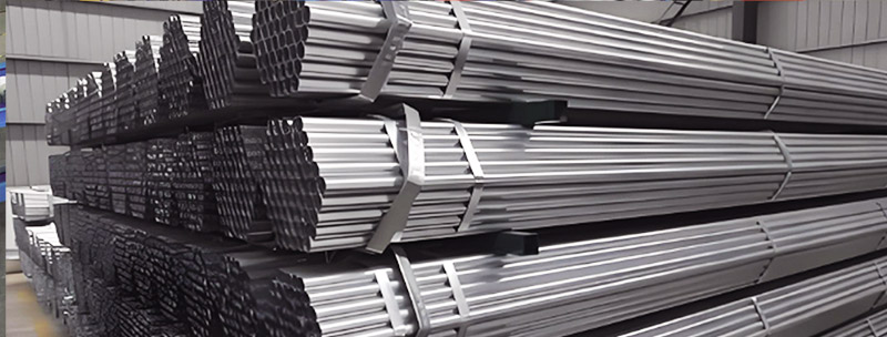
A steel coil processing line converts coiled metal into strip, sheet, profiles, panels, tubes, or formed components. The exact configuration depends on the finished product and may include:
- Almacenamiento de bobinas
- Coil transfer equipment
- Coche helicoidal
- Desenrollador
- Peeler or threading table
- Straightener or leveler
- Servorrealimentador
- Strip joining equipment
- Punching equipment
- Accumulator or loop
- Máquina perfiladora
- Welding or secondary processing
- Flying or stop-to-cut system
- Run-out conveyor
- Apilador
- Baling equipment
- Colección de chatarra
- Inspection station
Jinbolida equipo auxiliar de la máquina formadora includes coil transfer storage systems, strip shearing and end-welding equipment, intelligent blanking robots, and profile baling machines. These supporting systems can materially change the required floor space and movement pattern of the complete line.
La respuesta directa: ¿Qué hace que un diseño de procesamiento de bobinas de acero sea más seguro?
A safer layout keeps hazardous movements predictable and separates people from uncontrolled material, suspended loads, moving strip, rotating machinery, and mobile vehicles.
The layout should provide:
- A defined coil-storage and preparation zone
- A direct transfer path between storage and the uncoiler
- Enough space for coil loading without crossing routine pedestrian routes
- Controlled strip-threading access
- Guarded accumulator or loop areas
- Straight finished-product discharge
- Separate locations for inspection and rejected material
- Permanent maintenance and emergency-access routes
- Planned scrap removal
- Clearly separated crane, forklift, and pedestrian movements
Safety should be based on a site-specific risk assessment and applicable local requirements. A general layout guide cannot replace engineering review or regulatory compliance.
Comience con un mapa de flujo de materiales
Before placing machines on a drawing, map how material enters, moves through, and leaves the factory.
A practical material-flow study should include:
- Delivery vehicle arrival
- Coil unloading
- Incoming-material inspection
- Almacenamiento de bobinas
- Coil staging
- Transfer to the uncoiler
- Strip threading
- Continuous processing
- Finished-product discharge
- Inspección dimensional
- Accepted-product storage
- Nonconforming-product quarantine
- Scrap and slug removal
- Finished-product loading
This sequence should be drawn using actual equipment dimensions, load envelopes, turning radii, crane coverage, and safety-clearance requirements.
Evite cruzar rutas de flujo
Where possible, raw material should enter at one end of the steel coil processing line and finished products should leave from the other. This reduces cross-traffic and unnecessary handling.
If coils, finished profiles, forklifts, scrap containers, and pedestrians repeatedly cross the same area, the layout depends too heavily on operator attention.
Considere tanto la frecuencia como el tamaño
A large maintenance component may move only occasionally, while scrap bins or finished profiles may move several times per shift. High-frequency routes deserve priority because even a small inconvenience becomes a repeated exposure.
Planifique primero el área de almacenamiento de bobinas
Steel coils contain significant stored energy and can move unexpectedly if they are not restrained. Their weight, width, orientation, packaging, and structural condition should influence the storage method.
The Government of Ontario’s steel-coil storage and handling alert warns that improperly handled or stored coils can tip, collapse, fall, or cause crushing hazards. It also emphasizes planning for lifting, carrying, placement, storage, and removal.
Defina la orientación de la bobina
Coils are commonly stored with the axis horizontal or vertical, depending on material and handling practice.
| Storage orientation | Potential advantage | Layout consideration |
|---|---|---|
| Eye horizontal | Compatible with many coil cars and mandrel uncoilers | Requires reliable chocks or engineered supports |
| Eye vertical | May suit some packaging and lifting methods | Requires suitable lifting and transfer equipment |
| Individual rack or cradle | Defines a stable storage position | Must be rated for coil size and load |
| Floor storage with restraint | Can be simple for limited inventory | Requires engineered placement and clear removal method |
The storage system should be designed by qualified personnel for the actual coil weights, widths, diameters, and building conditions.
Reserve una posición de cuarentena
Do not mix damaged, unidentified, or nonconforming coils with released production material. A defined quarantine area prevents accidental use while keeping damaged coils away from normal traffic.
Mantenga el almacenamiento alejado de infraestructuras vulnerables
Coils should not obstruct:
- Gabinetes eléctricos
- Fire equipment
- Salidas de emergencia
- Building columns requiring inspection
- Utility isolation points
- Drainage routes
- Pedestrian doors
- Maintenance-access panels
Diseñe una zona de carga de bobinas controlada
Coil loading is one of the most safety-critical activities in steel coil processing. The movement may involve an overhead crane, C-hook, coil grab, forklift attachment, or transfer cart.
Defina la envolvente de carga
The layout should show more than the uncoiler footprint. It should include:
- Suspended-coil travel path
- Crane-hook approach
- Coil car movement
- Maximum coil diameter
- Posición de operador
- Temporary staging position
- Guard openings
- Mandrel expansion area
- Emergency retreat route
People not involved in loading should not need to pass beneath or near the suspended-load path.
Alinee la bobina con el desenrollador
A coil car or transfer device should approach the uncoiler in a controlled direction. Misalignment encourages repeated repositioning and can increase the time that the coil remains suspended or partially supported.
Jinbolida coil transfer and auxiliary-equipment category can be considered when planning automated storage, staging, and transfer around forming lines.
Proporcionar espacio para la eliminación de envases
Bands, wrapping, edge protectors, and pallets must be removed at a controlled stage. The area should allow safe access without placing personnel between the coil and fixed structures.
Released strip ends can move suddenly. The uncoiler and threading equipment should restrain the coil and strip during preparation.
Colocación de desenrolladores y roscado de tiras
The uncoiler begins the active production line and influences the position of every downstream machine.
Deje espacio alrededor del desenrollador
The layout should accommodate:
- Maximum coil diameter and width
- Expansión del mandril
- Coil car travel
- Hold-down arm movement
- Peeler or threading table
- Vigilancia
- Sensor access
- Lubricación
- Hydraulic service
- Removal of damaged material
- Emergency intervention under isolation
Placing the uncoiler too close to a wall may save apparent floor space but prevent maintenance, coil recovery, or safe cleaning.
Separe el subproceso normal del borrado de atascos
Normal threading should be possible using designed controls and handling equipment. Personnel should not need to reach into pinch points between the coil, peeler, straightener, or feeder.
Jam clearing is a separate non-routine activity and should follow an approved hazardous-energy-control procedure.
El CDC/NIOSH hazardous energy guidance notes that hazardous energy can be electrical, mechanical, hydraulic, pneumatic, chemical, or thermal. This is relevant to coil lines because stored strip tension and gravity can remain hazardous even after electrical power is switched off.
Plancha, alimentador y área de punzonado
The straightener, feeder, and punching system should normally share a consistent centerline. Poor alignment can create strip tracking problems while crowded access can make adjustment and inspection difficult.
Proporcionar acceso de ajuste
Operators may need to reach approved controls for:
- Straightener roll settings
- Guide width
- Feeder pressure
- Sensor adjustment
- Lubricación
- Punching recipes
- Tool-change preparation
These controls should be accessible without stepping over material, hoses, scrap, or moving components.
Planifique la eliminación de babosas y desechos
Punching operations create slugs, skeleton material, lubricant residue, and occasional damaged sections. Scrap containers should be removable without crossing the main operator position or stopping the entire line unnecessarily.
The removal route should account for:
- Container dimensions
- Filled weight
- Forklift access
- Drainage of cutting fluid where applicable
- Sharp edges
- Sorting requirements
- Replacement-bin staging
Mantenga la inspección fuera del camino de producción
Operators should not stand beside an unguarded process area to inspect a punched feature. Provide a sample-removal method and a nearby measurement station outside the hazardous zone.
Áreas de amortiguamiento, acumuladores y bucles
A buffer separates processes that do not operate at identical speeds. For example, a strip-joining or punching process may stop temporarily while roll forming continues using accumulated material.
Acuerdos comunes de amortiguación
| Buffer type | Función principal | Important layout issue |
|---|---|---|
| Free loop between machines | Absorbs short speed differences | Moving strip and unpredictable loop shape |
| Loop pit | Stores material below floor level | Fall protection, drainage, access, and rescue |
| Horizontal accumulator | Stores strip in a controlled structure | Larger footprint and guarding requirements |
| Vertical accumulator | Stores material using height | Building clearance and elevated maintenance |
| Coil transfer storage | Stages coils for faster changeover | Load movement and storage stability |
Por qué las áreas circulares necesitan protección
A moving strip loop can rise, fall, whip, or change position as line speed varies. It should not share an open walkway with operators.
The layout should identify:
- Maximum and minimum loop positions
- Sensor locations
- Guarded perimeter
- Access gate
- Inspection point
- Drainage or cleaning method
- Isolation procedure
OSHA’s machine-guarding guidance emphasizes protection from ingoing nip points, rotating parts, and other moving-machine hazards.
No utilice la zona de bucle como almacenamiento de repuesto
A fenced accumulator area may appear to contain unused floor space, but placing spare rollers, pallets, tools, or scrap inside can obstruct strip movement and maintenance access.
Roll Forming and Main Processing Zone
The central processing equipment may include forming stands, tube mills, welding systems, calibration units, or other profile-processing machines.
Jinbolida equipo de procesamiento de perfiles covers systems for C-channels, U-channels, Z-bars, square tubes, solar mounting profiles, and other formed products.
Provide Access on Both Sides Where Required
Roll forming lines often require access for:
- Roller inspection
- Spacer or cassette changes
- Shaft removal
- Guide adjustment
- Lubricación
- Fastener checks
- Sensor service
- Limpieza
- Alignment measurement
A narrow gap between the machine and wall may prevent tooling removal even when a person can physically walk through it.
Account for Tool-Handling Equipment
Heavy rollers, shafts, dies, and cassettes may require:
- Jib crane
- Overhead crane
- Forklift
- Tool cart
- Lifting beam
- Mobile platform
The layout should show how tooling reaches the machine without passing above occupied workstations or colliding with guards and utilities.
Keep Utilities Organized
Electrical cables, hydraulic lines, compressed-air pipes, coolant systems, and data connections should not create floor-level trip hazards or block maintenance doors.
Overhead or protected routing may improve access, but it must remain serviceable and comply with applicable requirements.
Finished-Product Discharge and Collection
The exit of the steel coil processing line is often underestimated. A machine producing long profiles may require more discharge space than the forming section itself.
Calculate the Real Discharge Length
The exit area should include:
- Maximum finished-product length
- Cut-off unit
- Run-out conveyor
- Product separation
- Stacking equipment
- Bundle formation
- End-stop movement
- Sampling position
- Finished-bundle removal
- Rejected-part removal
If a line produces 12-meter profiles, the layout needs more than 12 meters after the shear. It also requires room for conveyor structures, stops, access, stacking, and removal equipment.
Prevent Unsupported Product Drop
Long or thin profiles can bend, twist, or swing if they are discharged without proper support. This can damage the product and create struck-by hazards.
The run-out system should match:
- Profile length
- Section stiffness
- Velocidad de línea
- Cut-off method
- Peso del producto
- Stacking pattern
Separate People from Automatic Stacking
A robot, pusher, lift table, or stacking arm may create a large movement envelope. Physical guards, interlocked access, presence-sensing devices, or other protective measures should be selected through the machine’s risk assessment.
Plan a Dedicated Inspection Area
Inspection should be part of the material flow, not an improvised activity performed wherever space is available.
What the Inspection Area May Need
- Level reference table
- Profile-support fixtures
- Calipers and micrometers
- Height gauge
- Surface plate
- Go/no-go fixtures
- Hole-pattern gauges
- Computer or record station
- Controlled lighting
- Storage for accepted samples
- Quarantine position for rejected profiles
The inspection table should be long enough or suitably supported for the dimensions being measured. Placing a long profile on uneven supports can create misleading bow or twist results.
Keep Measurement Equipment Away from Vibration
Precision instruments should not be placed directly beside heavy punching, cutting, or material-drop points. Vibration, oil, debris, and uncontrolled temperature can reduce measurement reliability.
For tooling-related dimensional control, the article Cómo el mecanizado CNC de alta precisión mejora las herramientas de conformado de rollos explains how roller geometry, runout, surface finish, heat treatment, and inspection affect finished profiles.
Design the Finished-Goods Removal Route
A completed bundle must leave the discharge area before it blocks production.
The layout should answer:
- How is the bundle secured?
- What equipment lifts it?
- Does a forklift approach from the side or end?
- Can the load turn without entering a pedestrian route?
- Where is the next bundle staged?
- How are long products protected from collision?
- Is there a separate location for rejected material?
- Can removal occur while the line continues operating?
The discharge zone should not become temporary warehouse space unless it was designed for that purpose.
Separate Pedestrians, Forklifts, and Cranes
Traffic separation is one of the most important factory-layout decisions.
Pedestrian Routes
Walkways should:
- Lead directly to normal workstations
- Avoid suspended-load zones
- Avoid forklift turning areas
- Remain clear during production
- Provide access to emergency exits
- Use protected crossing points where routes must intersect
- Remain visible under normal lighting
Forklift Routes
Forklift paths should account for:
- Vehicle width
- Load width and length
- Turning radius
- Reversing visibility
- Floor condition
- Doorway clearance
- Intersection control
- Staging locations
- Pedestrian crossings
Crane Routes
The crane travel area should consider:
- Coil-transfer path
- Cambios en las herramientas
- Maintenance lifts
- Building columns
- Lighting and utilities
- Other cranes
- Restricted areas below suspended loads
The HSE publication on steel storage and handling safety discusses common hazards associated with unloading, storage systems, workplace transport, mechanical lifting, lifting accessories, and access arrangements.
Maintenance Access Must Be Designed, Not Left Over
Maintenance space should not be whatever remains after production equipment is placed.
Every major component needs access for inspection, removal, repair, or replacement.
Create a Maintenance-Access Matrix
| Equipo | Routine access | Major maintenance requirement |
|---|---|---|
| Desenrollador | Lubrication, sensors, hydraulic checks | Mandrel or drive removal |
| Straightener | Roll cleaning and adjustment | Roll or bearing replacement |
| Servorrealimentador | Pressure and encoder checks | Drive or roller replacement |
| Punching unit | Tool inspection and slug removal | Die or cylinder replacement |
| Rollo ex | Alignment, lubrication, fasteners | Shaft, roller, or stand removal |
| Cut-off unit | Blade or die inspection | Tooling and actuator replacement |
| Apilador | Sensors and lubrication | Motor, chain, or lifting assembly removal |
| Control cabinet | Filters and electrical inspection | Component replacement and testing |
For each task, show:
- Technician working position
- Required tool space
- Component-removal direction
- Lifting-equipment position
- Isolation point
- Temporary component storage
- Route to the workshop
Avoid Blocking Guard Doors
Maintenance access gates and electrical-cabinet doors need permanent clearance. They should not open into forklift lanes or depend on moving stored material first.
Emergency Access and Escape Routes
The line layout should preserve safe access during normal production, maintenance, fire, material jams, and utility failure.
Verificar:
- Emergency-exit visibility
- Travel distance under local requirements
- Fire-equipment access
- First-aid access
- Emergency-stop reach
- Rescue access around loop pits
- Access for emergency responders
- Lighting during power loss
- Routes that do not pass beneath suspended loads
Emergency routes should not depend on a movable pallet, scrap bin, tool cart, or finished bundle remaining in the correct position.
Noise, Lighting, and Environmental Conditions
Material flow is not the only layout consideration. The placement of noisy, oily, or debris-producing equipment affects both safety and inspection quality.
Ruido
Punching, cutting, material impact, and scrap handling may create high noise levels. Enclosures, barriers, isolation, or distance can reduce exposure, but the correct measures depend on site assessment.
Iluminación
Operators need suitable lighting for:
- Identificación de bobinas
- Strip threading
- Inspección de superficies
- Cambios de herramientas
- Medición
- Reading control panels
- Detecting leaks or damage
Lighting fixtures should not interfere with cranes or maintenance lifting.
Oil and Drainage
Lubricants and hydraulic fluids can create slip hazards. The floor and drainage plan should prevent liquids from spreading into walkways or inspection areas.
Compare Three Common Layout Approaches
| Layout approach | Ventaja principal | Main challenge | Suitable situation |
|---|---|---|---|
| Straight-through line | Clear material direction and simple discharge | Requires a long building bay | Continuous high-volume processing |
| Líneas paralelas | Shared utilities and supervision | Cross-traffic and maintenance congestion | Multiple related product lines |
| U-shaped material flow | Entry and exit can be near one logistics area | More transfers and turning points | Restricted building geometry |
| Line with external coil staging | Keeps heavy coil storage away from operators | Requires coordinated transfer timing | High coil inventory or crane limitations |
A straight line is not automatically the safest option, and a compact layout is not automatically efficient. The correct design depends on the building, product length, coil logistics, production frequency, and handling equipment.
Build the Layout Around Operating States
A line has more than one physical condition. The layout should be reviewed under:
- Normal automatic production
- Coil change
- Strip threading
- Cambio de producto
- Reemplazo de herramientas
- Jam clearing
- Preventive maintenance
- Major component removal
- Scrap-bin exchange
- Finished-bundle removal
- Emergency evacuation
Equipment that appears accessible when stopped may become blocked by a full coil, extended stacker, open guard, or finished bundle.
Digital Layout Review Before Installation
A scaled 2D drawing is the minimum requirement. A 3D model can provide additional value by showing:
- Crane-hook clearance
- Guard-door movement
- Operator reach
- Tooling-removal paths
- Elevated platforms
- Cable trays
- lighting conflicts
- Finished-product envelopes
- Maintenance lifting
The model should use actual supplier drawings rather than simple rectangles representing machine footprints.
Conduct a Cross-Functional Review
Include representatives from:
- Producción
- Mantenimiento
- Seguridad
- Calidad
- Logística
- Electrical engineering
- Civil engineering
- Equipment manufacturer
- Factory management
Each group sees different risks. Maintenance may identify an inaccessible motor, while logistics may notice that a forklift cannot remove the finished bundle without reversing through a pedestrian route.
Pre-Approval Layout Checklist
Before approving the steel coil processing line layout, confirm:
Coil Handling
- Coil weights and dimensions are defined.
- Storage supports are appropriately engineered.
- Quarantine space is available.
- Crane or transfer paths are clear.
- Coil loading does not cross routine pedestrian traffic.
- Packaging removal has a controlled location.
Processing Line
- All equipment uses one verified centerline.
- Guarding envelopes are shown.
- Strip threading can be performed through designed controls.
- Loop and accumulator areas are protected.
- Scrap removal routes are defined.
- Utility access remains available.
Finished Products
- Maximum product length fits the discharge area.
- Long profiles remain supported.
- Automatic stacker movement is protected.
- Inspection has a dedicated area.
- Accepted and rejected material are separated.
- Bundles can be removed without blocking production.
Mantenimiento y seguridad
- Major components have removal paths.
- Electrical cabinets can open fully.
- Isolation points are accessible.
- Emergency exits remain clear.
- Pedestrian and forklift routes are separated.
- Fire and emergency equipment remains reachable.
Verify the Layout During Factory and Site Acceptance
The machine FAT should confirm equipment dimensions, guard operation, service points, discharge motion, and maintenance requirements before shipment.
The SAT should confirm:
- Final equipment position
- Alignment and anchoring
- Utility connection
- Guarding and access
- Traffic routes
- Coil-transfer operation
- Finished-product removal
- Emergency access
- Iluminación
- Drenaje
- Site-specific safety functions
El PV solar bracket roll forming machine FAT guide provides related acceptance-testing considerations for materials, dimensions, production speed, changeovers, controls, and safety.
Conclusión
A safer steel coil processing line layout creates a controlled path from incoming coil storage to finished-product removal. It does not rely on spare floor space, temporary storage habits, or repeated manual intervention.
The most important planning areas are:
- Coil storage and loading
- Strip threading and upstream processing
- Buffering and accumulator protection
- Finished-product discharge
- Inspection and quarantine
- Eliminación de desechos
- Pedestrian and vehicle separation
- Acceso de mantenimiento
- Emergency routes
Auxiliary equipment should be considered during the initial layout, because coil transfer, strip joining, automatic blanking, stacking, and baling can significantly alter material flow.
To plan a complete line, review Jinbolida’s forming and coil-handling auxiliary equipment o contact the engineering team with your coil dimensions, product drawings, production target, available building layout, and material-handling method.
Preguntas frecuentes
1. How much space should be left around a steel coil processing line?
There is no universal clearance because access depends on coil size, guards, tooling changes, electrical doors, component-removal paths, lifting equipment, and local requirements. Use actual machine drawings and review every operating and maintenance task rather than applying one general distance around the entire line.
2. Where should the coil-storage area be located?
It should provide a short, controlled transfer route to the uncoiler while remaining outside routine pedestrian and finished-product traffic. The floor, racks, cradles, or restraints must suit the coil loads. Include staging and quarantine positions so damaged or unidentified coils cannot enter normal production accidentally.
3. Why does a steel coil processing line need a buffer?
A buffer allows connected processes to operate at different instantaneous speeds. It may keep forming equipment running during strip joining, punching, or another temporary interruption. However, moving strip inside a free loop, pit, or accumulator creates hazards that require controlled access, guarding, sensing, and maintenance planning.
4. How should long finished profiles be handled at the line exit?
Use a run-out and collection system designed for the maximum profile length, weight, stiffness, and line speed. The product should remain supported during cutting and discharge. The layout must also provide space for stacking, sampling, bundle preparation, rejection handling, and safe removal without blocking production.
5. What maintenance access should be included in the layout?
Provide permanent access for routine inspection and enough space for major component removal. Check the required path for rollers, shafts, motors, dies, cylinders, and electrical parts. Also reserve technician positions, lifting-equipment locations, isolation access, tool space, and temporary placement areas for removed components.
 Spanish
  English
  Arabic
  Russian
  French