
Machine de formage de rouleaux de support photovoltaïques pour acier à haute résistance
Table des matières
Introduction
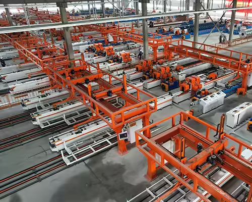
Solar mounting structures must remain stable under long-term outdoor loads, while manufacturers also need to control material use, profile weight, production efficiency, and component consistency. These requirements are making material specification an increasingly important part of photovoltaic bracket manufacturing.
For a PV bracket roll forming machine, changing from conventional steel to a higher-strength grade is not simply a raw-material substitution.
Higher yield strength changes how the strip behaves during bending. It can increase forming force, increase springback, affect shaft and bearing loads, change punching requirements, influence straightening, and place greater demands on tooling design and machine rigidity.
This means a machine that successfully forms a 2.0 mm conventional galvanized steel channel should not automatically be assumed to process a 2.0 mm higher-strength steel profile under exactly the same conditions.
WorldAutoSteel notes that higher-strength sheet requires greater roll forming force and greater compensation for springback, while machine design may require larger shaft diameters to handle increased loads.
For photovoltaic bracket manufacturers, the practical question is therefore not simply:
What is the maximum thickness of the machine?
Une question plus utile est la suivante
What material strength, thickness, profile geometry, punching pattern, tolerance, and production speed has the complete line actually been designed to process?
Pourquoi l'acier à haute résistance est important dans les structures de montage solaire
Photovoltaic racking is a structural system rather than a decorative metal assembly.
The U.S. Department of Energy describes PV mounting structures as systems that must provide stable support and withstand environmental conditions such as wind, weather, and corrosion. Ground-mounted racking commonly uses steel, often galvanized or otherwise protected for outdoor service.
More recent DOE guidance also emphasizes racking resistance to high wind, vibration, structural movement, and the integrity of critical fastened joints.
For mounting-system engineers, one way of meeting structural requirements can be through material grade and cross-sectional design.
Higher-strength steels may make it possible to redesign certain components, but the final result always depends on:
- limite d'élasticité,
- résistance à la traction,
- épaisseur,
- géométrie de section,
- local buckling behavior,
- envergure,
- conception de connexion,
- wind and snow loads,
- foundation conditions,
- and applicable structural requirements.
The manufacturing line does not determine whether a higher-strength material is structurally appropriate. That decision belongs to the mounting-system engineering process.
However, once a higher-strength grade is specified, the roll forming equipment needs to be capable of processing it consistently.
Une force élevée ne signifie pas la même chose qu’une épaisseur plus grande
One of the most common mistakes when specifying roll forming equipment is to describe material capability only by thickness.
Par exemple:
Material thickness: 1.5–3.0 mm
This information is incomplete.
Two steel coils can both be 2.5 mm thick but require different forming forces because their yield strengths differ significantly.
Machine engineering should therefore consider:
thickness + material strength + strip width + profile geometry
plutôt que l'épaisseur seule.
A wide, high-strength strip with several deep bends and return lips can place substantially more load on the forming system than a narrow, simple profile made from lower-strength steel at the same nominal thickness.
This affects equipment such as JBLDIE’s Machine de formage de supports solaires photovoltaïques, where the machine configuration should be matched to the actual bracket cross-section and material range.
Quels changements lorsque la résistance de l’acier augmente ?
Higher-strength material can influence almost every stage of photovoltaic bracket production.
| Manufacturing Area | Effect of Higher-Strength Steel | Main Equipment Concern |
|---|---|---|
| Rouleau formant | Force de formation plus importante | Machine rigidity and drive capacity |
| Printemps | Usually more difficult to compensate | Tooling and calibration |
| Roller shafts | Higher loading | Shaft diameter and deflection |
| Roulements | Greater working loads | Capacity and service life |
| Outillage | More severe contact/loading | Design, wear and material |
| Perforation | Greater force required | Press capacity and die condition |
| Coupe | Greater cutting load | Cutter capacity and tool life |
| Redressage | More force may be required | Plage d'ajustement |
| Protection de surface | Galvanized coating still needs protection | Roll/guide condition |
| Changement | Material grade becomes part of setup | Recipes and first-piece inspection |
These effects should be considered together rather than independently.
L'acier à plus haute résistance nécessite plus de force de formage
Roll forming creates permanent deformation only after local stresses exceed the steel’s yield strength.
When yield strength increases, greater force is generally required to create the same permanent bend.
WorldAutoSteel’s technical guidance specifically notes that higher-strength sheet increases roll forming force requirements.
For equipment buyers, this has several implications.
A machine needs enough:
- frame rigidity,
- shaft strength,
- bearing capacity,
- gearbox capacity,
- motor capability,
- and tooling support
for the actual production condition.
Simply increasing motor power does not solve every problem.
If the shafts or stands deflect excessively under load, additional drive power can actually make dimensional instability more obvious.
The complete mechanical structure needs to match the forming force.
Le diamètre de l'arbre devient plus important
Roller shafts support the tooling and transmit forming force.
When the strip enters the rollers, the shafts are loaded.
If shaft stiffness is insufficient, the shaft can deflect slightly under production load.
This means the actual roll position while forming may differ from the position measured when the machine is empty.
Possible results include:
- inconsistent roll gaps,
- unequal flange dimensions,
- incomplete bends,
- profile opening variation,
- différences de pression de surface,
- and dimensional drift.
WorldAutoSteel notes that higher-strength material can require larger roll forming shaft diameters because forming loads increase.
For a PV bracket machine buyer, shaft specification should therefore be reviewed together with material strength rather than treated as an isolated machine parameter.
La rigidité du châssis de la machine est importante
Higher forming load also passes into:
- supports de rouleaux,
- machine base,
- attaches,
- roulements,
- adjustment mechanisms,
- and support structures.
If these components move under load, the tooling geometry changes.
A machine can appear perfectly aligned during installation but still produce variation when processing demanding material.
This is why the appropriate question is not only:
Is the machine heavy?
Machine weight alone does not prove useful rigidity.
The more relevant engineering questions include:
- How are the forming stands supported?
- What is the shaft span?
- How are shafts mounted?
- What bearing arrangement is used?
- Comment les écarts de roulis sont-ils ajustés ?
- How does the machine control movement under forming load?
These factors become increasingly important as material strength and profile complexity rise.
Springback devient un problème majeur de contrôle de qualité
Higher-strength steels can exhibit greater springback during cold forming.
Springback occurs when part of the elastic deformation recovers after the material leaves the forming force.
A flange that is formed under load may open after leaving the roller.
For photovoltaic channels, this can affect:
- angle de bride,
- return-lip angle,
- ouverture du canal,
- web-to-flange relationship,
- largeur hors tout,
- and connection geometry.
This is particularly important for lipped C-channels where several bends interact.
The tooling cannot always form the material directly to the nominal finished angle.
It may need to intentionally over-form selected bends so that after springback occurs, the profile settles closer to the required geometry.
Le surformage doit être conçu et non improvisé
Suppose a finished C-channel requires a nominal 90° flange.
If a particular material consistently springs open after leaving the rollers, the tooling may need to form beyond the target angle before release.
However, the correct amount of compensation depends on:
- qualité de l'acier,
- épaisseur,
- bend radius,
- forming history,
- profile geometry,
- et conception d'outillage.
Operators should not attempt to compensate for high-strength material simply by tightening every stand.
Excessive pressure can introduce:
- marques de surface,
- additional longitudinal stress,
- usure d'outillage,
- bearing load,
- onde de bord,
- and profile distortion.
Springback compensation should be built into the forming strategy.
La conception de motifs floraux devient plus importante
The flower pattern describes how the profile develops from flat strip to finished section through each forming station.
For a PV C-channel, a simplified sequence might involve:
flat strip → initial lip bends → flange development → deeper channel formation → controlled overbend → calibration
Higher-strength material can require more careful distribution of deformation across these stages.
If too much bending occurs in one stand, the line can develop:
- excessive force,
- edge strain,
- dommages à la surface,
- twist,
- instability,
- or premature tooling wear.
A more gradual progression may provide better control.
However, simply adding more forming stands is not automatically the solution.
Each stand should have a specific forming purpose.
The number of passes should be justified by:
- material strength,
- épaisseur,
- bend severity,
- profile depth,
- retourne les lèvres,
- tolerance,
- and required production stability.
Les profils de canal C sont particulièrement sensibles

PV mounting structures frequently use C-shaped or lipped C-shaped sections.
JBLDIE Machine de formage de rouleaux d'acier pour profilés en C pour supports photovoltaïques solaires is one example of equipment developed around this profile family.
A typical lipped C-channel contains several interacting dimensions:
- largeur de la bande,
- hauteur de bride,
- return-lip length,
- angle de bride,
- lip angle,
- bend radius,
- and channel opening.
Changing springback at one bend can change several finished dimensions simultaneously.
For example, if both flanges spring outward:
- opening width increases,
- lip positions change,
- overall section geometry changes.
This makes profile inspection more meaningful than simply measuring one bend angle.
Les chaînes U réagissent différemment

A U-channel usually contains fewer bends than a lipped C-section.
That can simplify the forming sequence.
However, higher-strength material still affects:
- flange springback,
- side-wall angle,
- section opening,
- rectitude,
- and forming load.
Factories manufacturing U-shaped photovoltaic supports can evaluate the corresponding Machine de formage de profilés en U pour supports photovoltaïques solaires alongside the actual material specification.
C and U profiles should not be treated as identical simply because both are open channels.
Return lips, section depth, bend radius, and material strength can produce very different machine requirements.
L'acier à haute résistance modifie également les exigences de poinçonnage
Photovoltaic brackets frequently contain:
- trous de montage ronds,
- fentes allongées,
- localisation des trous,
- connector openings,
- and other punched features.
When material strength increases, punching force requirements also change.
A punching system selected around conventional material should not automatically be assumed to handle stronger material at the same thickness, hole size, cycle rate, and tool life.
The required punching force depends on factors including:
- material shear strength,
- épaisseur,
- total cutting perimeter,
- number of holes punched simultaneously,
- dégagement d'outils,
- and die design.
This becomes particularly important in multi-station equipment.
Ne spécifiez pas la capacité de poinçonnage uniquement par tonnage hydraulique
Press tonnage is important, but it is not enough to evaluate a photovoltaic bracket punching system.
Buyers should also provide:
- actual hole drawings,
- number of simultaneous features,
- qualité matérielle,
- épaisseur,
- hole geometry,
- punching surfaces,
- temps de cycle requis,
- and tooling configuration.
A long slot has a different cutting perimeter from a small round hole.
Several holes punched simultaneously require different force from one isolated feature.
Higher-strength material can increase load further.
JBLDIE Équipement de poinçonnage de racks photovoltaïques solaires includes multi-station configurations, but the correct number and capacity of stations should be determined from the actual finished bracket rather than from the assumption that more stations are always better.
Punch and Die Wear mérite plus d’attention
Higher material strength can also increase demands on punching tooling.
As punches and dies wear, manufacturers may begin to see:
- larger burrs,
- changing hole dimensions,
- rough slot edges,
- increased punching load,
- poor slug separation,
- or abnormal tool noise.
This becomes a quality and maintenance issue.
A profile may still have perfect roll formed dimensions but become unacceptable because its mounting holes deteriorate.
Tooling condition should therefore be connected with product inspection.
Instead of waiting for a punch to fail, factories can monitor:
- burr development,
- feature dimensions,
- position du trou,
- tooling cycles,
- and visual tool condition.
La position du trou doit encore être contrôlée après le formage
When punching occurs before roll forming, higher-strength material does not remove the relationship between punching and subsequent deformation.
A hole placed near a bend can still move relative to the finished profile geometry.
Springback can change the final location of the flange or web around that feature.
For this reason, the final quality check should measure:
finished hole position relative to finished profile geometry
plutôt que seulement:
punched hole position on the original flat strip.
This is especially important where mounting holes interact with clamps, connectors, fasteners, or project-specific installation interfaces.
La charge de coupe augmente également
The cut-off section needs to separate the finished high-strength profile repeatedly.
Greater material strength can affect:
- cutting force,
- blade loading,
- die wear,
- cut cycle,
- burr formation,
- and finished-end geometry.
For a complex C-channel, the cut-off tooling also needs to support the three-dimensional section during the stroke.
If support is insufficient, the profile may deform at the end.
Cela peut créer:
- crushed lips,
- local opening change,
- fin de la fusée éclairante,
- or surface marks.
The cutter should therefore be engineered around both profile geometry and material grade.
Straightening High-Strength PV Profiles
Roll formed profiles may require final correction for:
- arc,
- camber,
- et tordre.
High-strength material can resist this correction more strongly.
An adjustable straightening system needs enough working range to make controlled changes without introducing severe local deformation.
However, the straightener should not be used to hide an unstable forming process.
If a C-channel leaves the final forming stand with severe twist, investigate:
- bande centrale,
- écarts de roulis,
- tooling alignment,
- déflexion de l'arbre,
- material camber,
- and left/right forming balance
before applying extreme straightening.
The profile should arrive at the correction section reasonably stable.
Higher Strength Can Change the Machine’s Useful Speed
A machine may have a published maximum mechanical speed, but the useful speed for higher-strength steel can be different.
At higher speed, the line must maintain stable:
- strip entry,
- poinçonnage,
- formage,
- découpage,
- et déchargement.
Greater forming load can make vibration or deflection more noticeable.
High-speed operation can also expose:
- guide instability,
- mouvement d'outillage,
- servo timing issues,
- punching-cycle limitations,
- and cutting synchronization problems.
The correct production speed is therefore the speed at which qualified brackets can be produced consistently.
Maximum meters per minute should not be evaluated independently from material grade and finished-product quality.
Actual Capacity May Be Limited by Punching Rather Than Forming
This is especially important in photovoltaic bracket production.
Consider two channels made from the same high-strength steel.
Profil A
Contains a small number of repeated web holes.
Profil B
Contains round holes, long slots, side holes, and several connection patterns.
The roll forming section may process both profiles similarly.
Profile B can still have substantially lower finished output because punching requires more cycles.
Actual line capacity should therefore be calculated from:
feeding + punching + forming + cutting + unloading
rather than only roll forming speed.
Higher-Strength Steel Can Make Changeover More Complex
A production line may process several:
- profiles,
- épaisseurs,
- nuances d'acier,
- and hole patterns.
Changing material strength may require changes to:
- écart de roulis,
- over-forming,
- straightener setting,
- punching parameters,
- configuration de coupe,
- and production speed.
Material grade should therefore become part of the product recipe.
A useful production record might contain:
Profile C41
Steel Grade A
Thickness 2.0 mm
Punching Program 03
Roll Setup A
Straightener Setting B
Cut Length 6000 mm
If another grade is introduced, a separate verified setup may be needed.
Do Not Assume the Same Roll Setting Works for Every Steel Grade
This mistake can create unstable production.
Suppose a factory develops stable C-channel production using one galvanized steel specification.
Later, a higher-strength grade with the same nominal thickness is loaded.
The operators leave every machine setting unchanged.
They may then see:
- opening width increase,
- flange angles change,
- more twist,
- greater cutting load,
- and different punching behavior.
The machine has not suddenly become inaccurate.
The material has changed.
This is why material identification needs to remain connected to machine setup.
First-Piece Inspection Becomes More Important
After a significant material change, the first finished bracket should be inspected before continuous production begins.
For a C-channel, useful measurements include:
- largeur de la bande,
- hauteur de bride,
- longueur des lèvres,
- lip angle,
- largeur d'ouverture,
- dimensions des trous,
- position du trou,
- longueur coupée,
- rectitude,
- twist,
- et état de surface.
One part is still not enough.
Several consecutive components should be measured to confirm that the line is stable.
High-strength material can reveal machine movement or setup inconsistency that may be less visible with easier-to-form material.
Test Material Matters During FAT
Factory Acceptance Testing should use representative material whenever practical.
Testing a high-strength-steel production line using only softer conventional steel gives limited information.
The actual material influences:
- forming force,
- retour élastique,
- poinçonnage,
- redressage,
- découpage,
- and machine loading.
A meaningful FAT should therefore define:
Matériel
Actual or representative grade and thickness.
Profil
Representative high-load cross-section.
Perforation
Actual or representative hole pattern.
Vitesse
Agreed production condition.
Inspection
Finished-profile acceptance dimensions.
This is much more useful than demonstrating the machine without material or at extremely low speed.
What Buyers Should Ask About High-Strength Steel Capability
When evaluating a PV bracket roll forming machine, buyers should ask more detailed questions than “Can it process high-strength steel?”
Les questions utiles comprennent notamment
- What yield-strength range was the machine designed for?
- Which profile drawing was used for the calculation?
- What is the maximum strip width at that material strength?
- What is the maximum thickness at that strength?
- How was required forming force determined?
- What shaft diameter is used?
- How are shaft deflection and roll-gap stability controlled?
- How many forming passes are used for the profile?
- Comment le retour de printemps est-il compensé ?
- Can over-forming be adjusted?
- What punching capacity is available for the actual hole pattern?
- How does higher material strength affect punching cycle time?
- What cut-off system is used?
- How is finished straightness controlled?
- What material will be used during FAT?
A supplier should review the actual part before giving a meaningful answer.
Maximum Thickness Claims Need Context
A statement such as:
Maximum thickness: 3 mm
does not tell the buyer enough.
Demander:
3 mm of what material?
And:
3 mm in which profile?
The machine may be capable of forming 3 mm material in a relatively shallow U-profile but not necessarily a much wider deep-lipped section at the same speed.
A more useful machine capability statement connects:
material grade + thickness + strip width + finished profile
to the production requirement.
This is one of the most important procurement lessons when higher-strength steel is involved.
How to Compare Two PV Bracket Machines
Instead of comparing specification sheets line by line, use a real finished product.
Send the same drawing and material specification to both suppliers.
Then compare:
| Buyer Question | Machine A | Machine B |
|---|---|---|
| Material yield strength supported | ||
| Profile thickness range | ||
| Diamètre d'arbre | ||
| Number of forming passes | ||
| Springback strategy | ||
| Configuration du poinçonnage | ||
| Cut-off method | ||
| Qualified production speed | ||
| Méthode de basculement | ||
| FAT material | ||
| Finished tolerances | ||
| Protection de surface |
This creates a much more meaningful comparison than looking only at motor power, machine weight, or nominal speed.
High-Strength Steel and Galvanized Coatings
Higher-strength PV support material can still use galvanized or other protective coating systems depending on the component specification.
This means the production line needs to manage two requirements simultaneously:
Greater mechanical forming demand
et
surface protection.
Increasing roller pressure to handle stronger steel can increase the risk of:
- coating marks,
- rayures,
- local polishing,
- or excessive contact.
Tooling surfaces therefore need appropriate:
- finish,
- cleanliness,
- alignement,
- and pressure control.
A high-strength profile that meets dimensions but leaves the line with avoidable coating damage is not a successful production result.
Tooling Material and Wear Need to Match the Production Program
Rollers process every meter of material produced by the line.
As material strength and production volume rise, tooling condition becomes increasingly important.
Wear can gradually change:
- effective roll geometry,
- position de pliage,
- écart de roulis,
- et qualité de surface.
Manufacturers should establish inspection procedures for:
- roll surfaces,
- critical bend rolls,
- rouleaux latéraux,
- arbres,
- roulements,
- guides,
- punches,
- dies,
- and cutting tools.
Finished-product dimensional trends can provide early signs of tooling wear.
For example, if opening width gradually changes despite using the same material batch and machine recipe, tooling or mechanical condition should be investigated.
Maintenance Data Becomes More Valuable
A high-utilization PV bracket factory can connect maintenance information with production data.
Les dossiers utiles comprennent :
- qualité matérielle,
- machine hours,
- quantité de production,
- roll inspection,
- punch cycles,
- die condition,
- bearing replacement,
- cutting-tool maintenance,
- and dimensional inspection.
This allows maintenance to move from emergency repair toward planned intervention.
A worn punch can be serviced before hole burr exceeds the acceptance limit.
A roll can be inspected before gradual dimensional drift becomes a large batch-quality problem.
The value comes from connecting equipment condition with actual product results.
High Wind and Structural Requirements Increase the Importance of Manufacturing Consistency
The U.S. Department of Energy’s recent guidance on PV system installation and commissioning emphasizes racking capable of resisting high wind, vibration, torsional movement, and structural instability.
The mounting-system engineer determines the structural design required to meet these conditions.
The manufacturer then needs to reproduce those engineered components consistently.
That means profile production should maintain the specified:
- coupe transversale,
- trous,
- épaisseur de paroi,
- longueur coupée,
- coating condition,
- and connection interfaces.
Higher-strength material can contribute to a structural design only if the manufacturing process preserves the required geometry.
Material specification and production accuracy therefore need to be managed together.
Higher Strength Does Not Replace Good Profile Design
It is important not to assume that increasing material strength automatically solves structural issues.
A solar mounting member can still fail to perform as intended if:
- its section is inappropriate,
- local buckling is not considered,
- fastener locations are wrong,
- holes weaken critical regions,
- profile dimensions drift,
- connections are poorly designed,
- or corrosion protection is insufficient.
The profile should be engineered as part of the complete photovoltaic mounting structure.
The roll forming line’s role is to reproduce that design consistently.
Equipment selection should therefore follow completed or sufficiently developed engineering drawings rather than attempt to define the structural system through machine capability alone.
When a Dedicated High-Strength Profile Line May Make Sense
A dedicated production line can be useful when a manufacturer produces:
- one main structural profile,
- large volumes,
- stable material grade,
- repeatable hole patterns,
- and long production campaigns.
The machine and tooling can then be optimized around that product.
Advantages may include:
- fewer adjustment points,
- configuration plus simple,
- repeatable forming,
- and easier process standardization.
For manufacturers serving many projects with changing specifications, a more flexible line may make more sense.
The appropriate strategy depends on production mix.
When Flexible Tooling Is More Important
A factory supplying several solar projects may need to change:
- profile width,
- hauteur de bride,
- épaisseur du matériau,
- qualité de l'acier,
- motif de trou,
- et longueur finie.
Adjustable or interchangeable tooling can help.
However, flexible tooling should still be evaluated under high-strength production conditions.
The questions are:
- Does adjustment remain rigid under load?
- Are both sides positioned repeatably?
- Can springback settings be restored?
- Are mechanical references documented?
- Is first-piece inspection practical?
Flexibility without repeatability creates more setup work rather than less.
Useful Production Information to Provide a Machine Supplier
Before equipment engineering begins, buyers should provide a complete technical package.
Profile Information
- finished cross-section,
- bend radii,
- dimensions de la bride,
- retourne les lèvres,
- critical tolerances.
Informations matérielles
- qualité de l'acier,
- limite d'élasticité,
- tensile strength where relevant,
- épaisseur minimale et maximale,
- coating specification,
- strip width.
Punching Information
- trous ronds,
- emplacements,
- dimensions des trous,
- lancer,
- surfaces to be punched,
- number of simultaneous features.
Production Information
- common finished lengths,
- batch sizes,
- product mix,
- target output,
- changeover frequency.
Information Qualité
- rectitude,
- twist,
- exigences de surface,
- dimensional acceptance,
- applicable product standards.
This gives the equipment supplier enough information to evaluate the complete production condition.
A Practical High-Strength PV Bracket Production Checklist
Before approving continuous production, verify:
Incoming Material
Confirm grade, thickness, width, coating, and coil identification.
Alimentation
Verify strip centerline and stable material movement.
Perforation
Check hole dimensions, burrs, pitch, and long-range position.
Formation
Inspect web, flange, lip, angle, opening, and profile symmetry.
Printemps
Confirm the finished unloaded profile rather than geometry inside the rollers.
Droiture
Check bow, camber, and twist.
Coupe
Inspect cut length and end deformation.
Surface
Check galvanized coating for scratches and tooling marks.
Répétabilité
Measure several consecutive profiles.
This process confirms whether the entire manufacturing system—not simply the roll former—can handle the selected higher-strength material.
Conclusion
UN PV bracket roll forming machine designed for higher-strength steel needs to manage significantly more than material thickness.
As steel strength increases, forming forces rise and springback becomes more important. Shafts, bearings, stands, frames, tooling, punching systems, straighteners, and cutters all need to work within the new load condition.
For photovoltaic C- and U-channel production, the effect is especially visible in flange angles, return lips, opening width, straightness, and punched connection features.
The most important procurement lesson is therefore simple:
Do not ask whether a machine can process “2 mm steel.”
Ask whether it can process the actual 2 mm steel grade, strip width, profile geometry, punching pattern, tolerance, and production speed required by your photovoltaic bracket.
High-strength material can support advanced structural designs, but only when the production line is engineered around its real forming behavior.
Machine rigidity, springback compensation, punching capacity, tooling wear, first-piece verification, and representative FAT should all be evaluated before continuous production begins.
FAQ
Can a standard PV bracket roll forming machine process high-strength steel?
Possibly, but it depends on the machine design, material yield strength, thickness, strip width, profile geometry, tooling, shaft capacity, and required speed. A machine’s maximum thickness rating alone is not enough to confirm suitability.
Why does high-strength steel create more springback?
Higher-strength steel generally requires greater stress to produce permanent deformation and can retain a larger elastic recovery component after forming. Tooling may therefore need greater over-forming and calibration.
Does high-strength steel require a larger roll forming machine?
Not necessarily in overall physical size, but it may require greater frame rigidity, larger or stronger shafts, suitable bearings, adequate drive capacity, and tooling designed for higher forming loads.
Does material strength affect photovoltaic bracket punching?
Yes. Higher-strength material can increase the force required to punch holes and slots and can influence tooling wear, burr condition, press capacity, and production cycle.
What should be tested during FAT for a high-strength PV bracket line?
FAT should use representative material and profile geometry where practical and verify forming, punching, cutting, straightness, surface condition, finished dimensions, production speed, and repeatability across multiple parts.
Planning High-Strength PV Bracket Production?
High-strength photovoltaic bracket production should be configured around the actual steel grade, thickness, strip width, profile drawing, hole pattern, springback, tolerances, and target output. Contactez JBLDIE to discuss your PV support profiles and production-line requirements.
 French
  English
  Arabic
  Russian
  Spanish