
CNC Control System Functions That Matter in Roll Forming
Table of Contents
A CNC control system can coordinate feeding, punching, forming, cutting and finished-product handling in a roll forming production line. However, the value of the system does not depend on the number of screens, buttons or advertised “smart” functions.
The most useful control functions solve specific production problems. They reduce setup errors, maintain position accuracy, coordinate machine movements, record alarms, support product changeovers and provide traceable production data.
Important functions include:
- Product recipe management
- Servo-feeding position control
- Punching-pattern programming
- Cutting-length control
- Line-speed synchronization
- Batch and production counting
- Alarm history
- Tool-life monitoring
- User-access management
- Material and production traceability
- Energy-consumption monitoring
- Remote diagnostics
- Data export and factory-system integration
A CNC control system should be evaluated as part of the complete mechanical process. It cannot compensate for worn tooling, incorrect roller alignment, unstable raw material or inadequate machine rigidity. The strongest production line combines stable mechanics with clear, reliable and maintainable control logic.
What Is a CNC Control System?
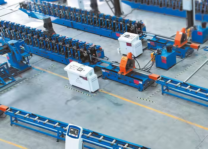
A CNC control system uses programmed instructions to control machine movements and production operations. The general concept of computer numerical control involves automated control of machine tools through coded or programmed commands.
In roll forming applications, the term “CNC control system” may refer to a combination of:
- PLC
- HMI touchscreen
- Servo drives
- Variable-frequency drives
- Motion controller
- Encoders
- Sensors
- Safety controller
- Industrial computer
- Network communication
- Cloud or remote-monitoring interface
These components perform different functions.
PLC
The programmable logic controller manages machine sequences, interlocks, signals and automatic operations.
It may control:
- Decoiler start and stop
- Leveler operation
- Punching sequence
- Hydraulic valves
- Cutter movement
- Stacker actions
- Alarm logic
HMI
The human-machine interface allows operators to:
- Select products
- Enter lengths
- Set batch quantities
- View alarms
- Adjust permitted parameters
- Monitor production status
The HMI should present useful production information without exposing unnecessary engineering settings to every operator.
Servo System
Servo motors and drives control precise movements such as:
- Strip feeding
- Punching position
- Flying cutting
- Adjustable roller axes
- Tool change
- Product transfer
CNC or Motion Controller
A dedicated motion controller may coordinate high-speed, multi-axis movements where a standard PLC cycle is insufficient.
The correct architecture depends on the speed, number of axes, required synchronization and equipment complexity.
Why Controls Matter in Roll Forming
A roll forming line converts continuous metal strip into profiles through multiple connected operations. The Roll Forming Machine Basics and Applications guide explains the general relationship between feeding, progressive forming and cutting.
The control system must ensure these operations occur in the correct order and at the correct position.
For example, a photovoltaic bracket line may need to:
- Unwind the coil.
- Level the strip.
- Advance a programmed distance.
- Punch a round hole.
- Advance another distance.
- Punch a long slot.
- Form the strip into a C-channel.
- Measure the finished length.
- Cut the product.
- Transfer it to the receiving area.
- Count the qualified piece.
If one command is late, duplicated or missing, the finished product may have an incorrect hole pattern or cut length.
Jinbolida’s Solar Photovoltaic Bracket Forming Machine range includes automated forming configurations for different photovoltaic profile types.
1. Product Recipe Management
Recipe management is one of the most valuable control functions for factories producing multiple products.
A recipe may store:
- Product code
- Product length
- Batch quantity
- Hole dimensions
- Hole spacing
- Punching sequence
- Cutting position
- Feeder movement
- Line speed
- Adjustable-axis position
- Inspection limits
- Tool identification
Instead of entering every parameter manually, an authorized operator selects the approved product recipe.
Reduce Setup Error
Manual data entry can create:
- Incorrect length
- Wrong hole pitch
- Missing punching station
- Wrong batch quantity
- Unsuitable speed
- Incorrect adjustable-axis position
A controlled recipe reduces repeated entry but does not eliminate the need for first-article inspection.
Recipe Version Control
When a drawing changes, the production recipe should also be updated.
Useful controls include:
- Recipe revision number
- Creation date
- Approval status
- Drawing reference
- Change history
- Authorized editor
- Previous-version archive
Operators should not be able to select an obsolete recipe without a clear warning.
Protect Critical Parameters
Some values may be adjusted during normal production, while others should require higher-level access.
For example:
- Batch quantity may be operator-adjustable.
- Hole position may require supervisor access.
- Servo calibration may require maintenance access.
- Safety settings should require authorized technical access.
2. Servo-Feeding Position Control
Servo feeding determines where the strip stops or moves for punching and cutting.
The control system should manage:
- Feed distance
- Acceleration
- Deceleration
- Speed
- Position confirmation
- Encoder feedback
- Slip detection
- Position correction
Position Accuracy Is a Complete System Result
High encoder resolution alone does not guarantee accurate hole positions.
Actual accuracy is affected by:
- Feeder roller grip
- Material surface
- Strip flatness
- Guide alignment
- Roller pressure
- Mechanical backlash
- Servo tuning
- Encoder installation
- Material acceleration
- Control logic
The system should be tested with real production material and full-length hole patterns.
Prevent Cumulative Error
A long profile containing repeated holes can develop cumulative error if each movement contains a small uncorrected deviation.
Possible control strategies include:
- Absolute position programming
- Reference-hole detection
- Registration sensors
- Periodic correction
- Encoder verification
- Non-cumulative movement calculation
The correct method depends on the product and production arrangement.
3. Punching-Pattern Programming
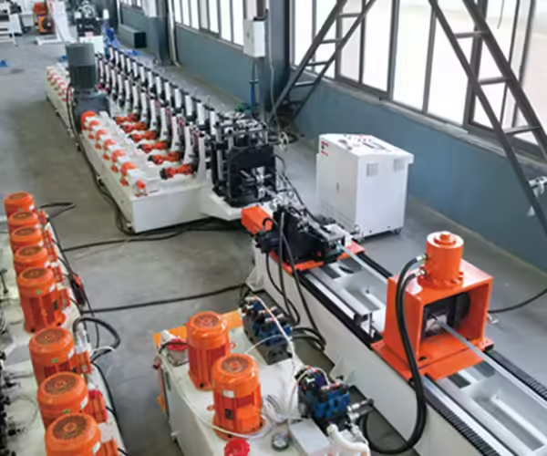
Photovoltaic brackets and construction profiles often contain several hole and slot combinations.
A CNC control system may allow users to program:
- Round holes
- Long slots
- Notches
- Embossed features
- Repeated groups
- Mirrored patterns
- Variable spacing
- Product-specific station selection
Jinbolida’s Solar Photovoltaic Rack Punching Equipment includes multi-station punching systems for different solar bracket components.
Tooling Still Defines Physical Capability
Software cannot create a feature that the mechanical tooling does not support.
For every recipe, confirm:
- Correct punch and die
- Material thickness range
- Required press force
- Tool clearance
- Station location
- Slug removal
- Tool-life status
The control system should prevent a recipe from activating an unavailable or incompatible tool where practical.
Simulate the Sequence
A preview screen can help operators confirm the expected hole pattern before processing the full coil.
Useful information includes:
- Product length
- Hole positions
- Station number
- Number of strokes
- Estimated cycle
- Cut position
The preview should supplement, not replace, drawing approval.
4. Cutting-Length Control
Cut-length control connects encoder measurement, line movement and the cutting system.
Depending on the machine, cutting may use:
- Stop-to-cut
- Flying cut-off
- Hydraulic die cutting
- Saw cutting
- Pre-cutting
- Servo tracking
Stop-to-Cut Control
The line decelerates and stops at the programmed position before the cutter acts.
The controller should verify:
- Zero-speed condition
- Correct position
- Cutter-ready signal
- Guard status
- Cut completion
- Tool return
Flying Cut-Off Control
A flying cutter must match the profile speed, complete the cut and return without interfering with the next product.
The system must coordinate:
- Line-speed feedback
- Cutter acceleration
- Synchronization position
- Cutting command
- Travel limit
- Return movement
- Next cycle
Poor synchronization may create length variation or tool impact.
Coordinate Holes with Cut Ends
The final hole-to-end distance is often assembly-critical. Punching and cutting should use a consistent reference strategy.
If the feeder and cutter rely on separate uncorrected measurements, the product may have accurate hole pitch but an incorrect final edge distance.
5. Line-Speed Synchronization
A complete roll forming line contains equipment with different mechanical limits.
The control system may coordinate:
- Decoiler
- Leveler
- Feeder
- Punching press
- Roll former
- Cutter
- Conveyor
- Stacker
Do Not Force Every Unit to One Speed
Some equipment operates continuously, while punching and cutting may work cyclically.
The system may use:
- Loop control
- Buffer zones
- Accumulator feedback
- Speed references
- Ready signals
- Interlocks
- Controlled line stops
A properly designed buffer can allow one section to pause briefly without stopping every machine.
Protect the Material
Poor synchronization can cause:
- Excessive strip tension
- Loose loops
- Material buckling
- Side movement
- Feeding error
- Surface scratching
- Uncontrolled coil rotation
Sensors and control logic should keep the strip within an approved tension or loop range.
CNC Control Functions and Manufacturing Value
| Control function | Production problem addressed | Important verification |
|---|---|---|
| Recipe management | Manual setup errors | Revision and access control |
| Servo positioning | Inaccurate holes and lengths | Full-product measurement |
| Pattern programming | Multiple product variants | Tooling compatibility |
| Cutting control | Length variation | Synchronization and calibration |
| Line-speed control | Unstable material flow | Test at normal production speed |
| Batch counting | Incorrect order quantity | Define accepted-count logic |
| Alarm history | Repeated unexplained stops | Clear time and reason records |
| Tool-life tracking | Sudden burr or tool failure | Link counts with real inspection |
| User permissions | Unauthorized changes | Role-based access |
| Traceability | Difficult defect investigation | Material and recipe identification |
| Energy monitoring | Unknown consumption | Machine state and product context |
| Remote diagnostics | Slow technical support | Secure controlled access |
| Data export | Isolated machine records | File format and field definitions |
6. Batch Counting and Production Records
A production counter appears simple, but its logic must be clearly defined.
Possible counts include:
- Feed cycles
- Punching cycles
- Cut cycles
- Total pieces
- Qualified pieces
- Rejected pieces
- Reworked pieces
- Bundle quantity
Counting every cut as a finished product can overstate output if defective pieces are not removed from the total.
Separate Total and Qualified Production
The system should allow quality staff or authorized operators to record rejected products.
A useful production record includes:
- Product code
- Recipe revision
- Material batch
- Start and finish time
- Total pieces
- Qualified pieces
- Rejected pieces
- Stop time
- Operator
- Tooling set
Batch Completion
When the required quantity is reached, the system may:
- Stop automatically
- Notify the operator
- Complete the current product
- Print or transmit a batch record
- Request quality approval
- Prepare the next recipe
The expected behavior should be defined before commissioning.
7. Alarm History and Downtime Recording
An alarm that appears and disappears without a record provides little value for maintenance.
Alarm history should store:
- Time
- Alarm code
- Description
- Machine state
- Product recipe
- Duration
- Acknowledging user
- Reset time
Write Clear Alarm Messages
“System fault” is not a useful maintenance instruction.
Better alarm messages identify the affected component and likely check, such as:
- Feeder position not reached
- Punch station 3 return sensor not detected
- Cutter home position timeout
- Decoiler loop below minimum
- Hydraulic pressure below limit
- Stacker area not clear
Messages should use terminology understood by operators and technicians.
Track Minor Stops
Repeated short stops can remove more production time than one rare breakdown.
The system should distinguish:
- Material stop
- Feeding stop
- Punching stop
- Forming stop
- Cutting stop
- Stacking stop
- Quality stop
- Safety stop
- Maintenance stop
The related guide Why Photovoltaic Bracket Roll Forming Lines Lose Output explains how minor interruptions affect qualified production. Update the internal link to the final article URL after publication.
8. Tool-Life and Maintenance Monitoring
Tool-life counters can help schedule inspection for:
- Punches
- Dies
- Cutting blades
- Saw blades
- Bearings
- Filters
- Lubrication
- Hydraulic oil
- Forming rollers
A Counter Is Not a Condition Sensor
A punch may wear faster when processing thick or high-strength material. Another tool may remain acceptable beyond the initial inspection interval.
Tool-life monitoring should combine:
- Cycle count
- Material
- Thickness
- Burr inspection
- Surface inspection
- Maintenance history
The control system should prompt inspection rather than automatically assuming that every tool fails at exactly the same cycle count.
Maintenance Modes
A controlled maintenance mode may allow:
- Low-speed jog
- Individual station movement
- Sensor testing
- Output testing
- Manual valve control
- Axis homing
These functions should be access-controlled and coordinated with the machine safety system.
9. User Access and Change Management
Different users require different permissions.
| User role | Typical access |
|---|---|
| Operator | Select approved recipe and run production |
| Supervisor | Adjust permitted production parameters |
| Quality | Record inspection and reject data |
| Maintenance | Jog equipment and test components |
| Engineer | Edit recipes and motion settings |
| Administrator | Manage users, backup and system configuration |
Record Parameter Changes
The system should record critical changes where practical:
- Previous value
- New value
- Time
- User
- Product recipe
- Reason or work order
This helps investigate why one shift or batch produced different results.
Avoid Shared Passwords
Shared credentials prevent meaningful accountability. Each authorized user or role should have appropriate access.
Access control should also prevent accidental changes to calibration, motion tuning and safety-related settings.
10. Production Traceability
Traceability connects a finished profile with its material and production conditions.
A traceability record may include:
- Coil number
- Material grade
- Supplier batch
- Product code
- Drawing revision
- Recipe revision
- Production date
- Machine
- Operator
- Tooling
- Inspection results
- Alarm history
When a dimensional or coating problem is found, this information helps define the affected production range.
Barcode or QR Integration
The control system may read or produce identifiers for:
- Raw-material coils
- Work orders
- Tooling sets
- Finished bundles
- Inspection records
The identification method should match the factory’s production and inventory systems.
11. Energy-Consumption Monitoring
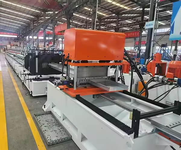
Energy monitoring can show how much electricity or other utility input the machine uses during:
- Production
- Idle time
- Setup
- Standby
- Alarms
- Maintenance
Jinbolida’s product range includes equipment with functions for recording production and energy-consumption data. The Forming Machine Auxiliary Equipment category can support production-line efficiency planning.
Energy per Qualified Product
Total energy per shift is useful, but energy per qualified piece or meter provides more operational context.
An increase may indicate:
- Longer idle time
- More rejected products
- Tool wear
- Excessive hydraulic operation
- Drive problems
- Poor production scheduling
- Frequent start-stop cycles
Add Production Context
Energy data should be linked with:
- Product
- Material
- Thickness
- Shift
- Qualified output
- Machine state
Without context, a higher reading may simply reflect a thicker material or different product.
NIST’s work on smart manufacturing emphasizes interoperable measurement, control and information technologies. For a roll forming factory, useful data should connect equipment performance with clear production decisions.
12. Remote Diagnostics
Remote diagnostics can help technical teams review:
- Alarm history
- PLC status
- Sensor signals
- Servo faults
- Program versions
- Production data
- Communication problems
It can reduce the time required to identify a problem, especially when the machine supplier and factory are in different locations.
Remote Access Is Not the Same as Remote Operation
Remote diagnosis should not allow uncontrolled movement of hazardous equipment.
Physical machine movement should remain subject to:
- Local safety status
- Guard condition
- Operator confirmation
- Controlled maintenance procedures
- Site authorization
Cybersecurity and Access Control
Remote connections should be intentionally designed rather than added informally.
The system owner should define:
- Who can connect
- When access is allowed
- What data can be viewed
- Whether changes are permitted
- How sessions are recorded
- How access is disabled
- Who approves software updates
- How backups are maintained
Factory IT and equipment engineering teams should agree on the connection method.
13. Data Export and Factory Integration
A control system may exchange information with:
- MES
- ERP
- Quality-management system
- Maintenance system
- Energy-management platform
- Warehouse system
Useful exported data may include:
- Work order
- Product code
- Batch quantity
- Production time
- Qualified output
- Rejection count
- Downtime
- Energy use
- Material batch
- Alarm history
Confirm the Interface Before Ordering
Ask the supplier to define:
- Communication protocol
- Available data fields
- Update frequency
- File format
- Network requirements
- Read and write permissions
- Responsibility for commissioning
A statement such as “MES compatible” is not enough without an interface specification.
Choosing the Right CNC Control Level
Not every line needs the same control architecture.
Basic Line
A basic system may include:
- PLC
- HMI
- Length setting
- Batch counting
- Basic alarms
- Manual adjustment
It may suit one stable profile and moderate production.
Flexible Multi-Product Line
A flexible system may add:
- Recipe management
- Servo feeding
- Multi-station punching selection
- Adjustable axes
- Change history
- Tool identification
- Product-specific inspection prompts
Integrated Smart Production Line
An integrated system may add:
- Multiple synchronized axes
- Automatic stacking
- Material tracking
- Energy monitoring
- Downtime recording
- Remote diagnostics
- Factory-system interface
- Production reporting
The required control level should follow the product mix and operational needs.
Questions to Ask the Control-System Supplier
Before confirming the line, ask:
- Which products and parameters can be stored as recipes?
- How are recipe changes approved and recorded?
- What is the servo-feeding control method?
- How is cumulative position error prevented?
- Which alarms are stored in history?
- Can downtime reasons be classified?
- How are rejected products recorded?
- Can tool-life counters be linked to products?
- Which user roles and permissions are available?
- What production data can be exported?
- How is energy consumption measured?
- What remote-diagnostic access is included?
- How are PLC and HMI programs backed up?
- Who owns the final program and documentation?
- How will the complete system be tested before shipment?
Factory Acceptance Test for the CNC Control System
The factory acceptance test should verify the control system under realistic production conditions.
Test:
- Recipe creation and selection
- User permissions
- Servo positioning
- Hole patterns
- Product lengths
- Batch counting
- Changeovers
- Alarm messages
- Emergency-stop response
- Power-loss recovery
- Tool-life prompts
- Data recording
- Energy monitoring
- Backup and restore
- Remote-diagnostic procedure
Use representative materials and product drawings. A control system that works only in manual demonstration has not proved production capability.
Common Control-System Mistakes
Adding Functions Without a Production Purpose
More screens and data fields increase complexity if nobody uses them.
Allowing Every User to Edit Recipes
Uncontrolled changes make product quality difficult to reproduce.
Recording Alarms Without Duration
Frequency alone does not show total production loss.
Counting Every Cut as a Qualified Product
Rejected and reworked pieces must be recorded separately.
Depending on Software to Correct Mechanical Problems
Control adjustments cannot permanently solve worn rollers, loose shafts or poor material alignment.
Offering Remote Access Without Governance
Connection methods, permissions and security responsibilities must be defined.
Failing to Provide Backups
PLC, HMI, servo and recipe programs should be backed up and version controlled.
Conclusion
The CNC control system functions that matter most in roll forming are those that improve repeatability, positioning, changeovers, diagnosis and traceability.
Recipe management reduces manual setup errors. Servo control supports accurate feeding. Pattern programming coordinates punching. Cutting control maintains length. Alarm history reveals recurring stops. Tool-life monitoring supports maintenance. Traceability connects finished products with material and production conditions.
Energy monitoring and remote diagnostics can provide additional value when they are linked to qualified output and controlled access.
Jinbolida develops automated solar photovoltaic bracket forming machines, punching systems and smart production-line solutions. Manufacturers can submit product drawings, control requirements, factory-system interfaces and production targets through the Jinbolida contact page for a customized evaluation.
FAQ
Is a PLC the same as a CNC control system?
Not exactly. A PLC typically manages machine sequences, inputs, outputs and interlocks, while CNC or motion control manages programmed positioning and coordinated axes. In roll forming, the complete control system may combine a PLC, HMI, servo drives, encoders and a motion controller under one operator interface.
Which CNC control function is most useful for multi-profile production?
Recipe management is especially useful because it stores approved lengths, hole patterns, batch quantities, speeds and adjustable positions for each product. However, the recipe must use version control and access permissions. A stored program reduces manual entry but still requires first-article dimensional verification after changeover.
Can a CNC control system prevent cumulative hole-position error?
It can help through servo positioning, encoder feedback, absolute programming and periodic correction. However, mechanical slippage, poor leveling, guide misalignment and unstable material can still affect accuracy. Position performance should be verified across the complete finished profile rather than only through a short feeder movement.
What production data should a roll forming line record?
Useful records include product code, recipe revision, material batch, total pieces, qualified pieces, rejected pieces, cycle time, downtime, alarm history, tooling set, operator and energy use. Data should support a specific quality, maintenance or planning decision instead of being collected without a defined purpose.
Is remote diagnosis safe for a roll forming machine?
Remote diagnosis can be useful when access is controlled, recorded and limited to authorized users. It should not allow uncontrolled hazardous movement. Local safety conditions, operator confirmation and site procedures must remain active. The factory should define connection methods, permissions, software updates and access termination.
 English
  Arabic
  Russian
  Spanish
  French