
¿qué hace que los soportes de montaje de paneles fotovoltaicos sean más fáciles de montar?
Tabla de contenido
PV panel mounting brackets may look like simple metal components, but small manufacturing variations can create significant installation problems. Incorrect hole spacing, profile twist, uneven flange dimensions or distorted cut ends can prevent rails, posts, connectors and fasteners from aligning correctly.
A mounting bracket that is easy to assemble is not defined only by its appearance. It must consistently match the approved drawing, fit related components and maintain the required geometry along its full length.
The manufacturing factors that have the greatest influence on assembly include:
- Consistent cross-sectional dimensions
- Accurate hole and slot positions
- Controlled straightness and twist
- Stable bend angles
- Repeatable cut length
- Clean punched and cut edges
- Protected coating surfaces
- Compatibility with connectors and fasteners
- Reliable production traceability
For manufacturers, assembly performance should be considered when selecting roll forming, punching, cutting and inspection equipment. The objective is not simply to produce a profile that looks correct. It is to produce components that connect without unnecessary force, drilling, trimming or field adjustment.
Cómo funcionan los soportes de montaje de paneles fotovoltaicos
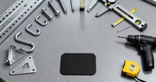
PV panel mounting brackets form part of the structure that positions and supports solar modules. Depending on the system design, they may connect modules to rails, rails to posts, profiles to roofs or structural members to foundations.
A photovoltaic mounting system may be installed on rooftops, ground structures, building façades or tracking systems. Each application uses a different combination of rails, brackets, clamps, posts, fasteners and connectors.
The U.S. Department of Energy’s overview of diseño de sistemas solares fotovoltaicos notes that mounting structures support and position PV arrays. Although structural design depends on the project, every mounting system relies on components that fit together according to the approved engineering requirements.
Common manufactured components include:
- Rieles de canal C
- U-channel profiles
- Canales de puntal ranurados
- Correas en forma de Z
- Rieles de montaje en techo
- Puestos de apoyo en tierra
- Miembros vigorizantes
- Placas conectoras
- Abrazaderas de módulo
- Placas base
- Tracker-support components
Jinbolida Máquina formadora de soportes para sistemas solares fotovoltaicos range includes equipment for producing C-channel, U-channel and related photovoltaic mounting profiles from coil material.
Comience con el montaje completo
A bracket should not be evaluated as an isolated component. Its dimensions interact with other parts of the mounting system.
Before production begins, manufacturers should review:
- Bracket drawing
- Mating component drawings
- Fastener sizes
- Connector geometry
- Module clamping zones
- Assembly sequence
- Allowable adjustment
- Structural tolerances
- Coating requirements
- Installation environment
A profile may meet its individual width tolerance but still be difficult to assemble if the connector was designed around a different datum or tolerance condition.
Utilice datos funcionales
Inspection points should relate to how the bracket is assembled.
For example, a hole may be dimensioned from:
- The cut end
- The profile centerline
- One flange
- A previously punched hole
- A formed edge
- A connector reference surface
The datum used in manufacturing should match the drawing. Otherwise, several individually acceptable dimensions may combine into an assembly problem.
Considere la acumulación de tolerancia
A mounting assembly may contain a rail, connector, post and several fasteners. Each part has its own variation.
If every component reaches the same extreme of its permitted tolerance, the combined result may prevent proper alignment. This is known as tolerance accumulation or tolerance stack-up.
Manufacturing teams should therefore identify which dimensions are functionally critical rather than applying the same tolerance to every feature.
1. Dimensiones transversales consistentes
The cross-section determines whether a connector, clamp or fastener can enter and seat correctly.
Important dimensions may include:
- Ancho web
- Altura de la brida
- Longitud del labio
- Apertura del canal
- Radio de curvatura
- Ángulo de curvatura
- Grosor del material
- Section depth
- Slot position relative to the profile
A small dimensional change can affect the way a nut, connector or clamp sits inside the channel.
Apertura de canal
For slotted strut and C-channel components, the channel opening must remain consistent. If it is too narrow, a connector nut may not enter or rotate. If it is too wide, the connector may not engage as intended.
Opening variation can result from:
- Incorrect roller gap
- Variación material-espesor
- Springback
- Worn tooling
- Movimiento del eje
- Incorrect straightening
- Setup changes
The production line should inspect the opening at several positions along the profile, not only at one end.
Dimensiones de bridas y labios
Flanges and lips often provide stiffness or retain internal connectors. Unequal flange dimensions can move the profile centerline and make hole alignment more difficult.
The forming process should produce balanced geometry on both sides where the drawing requires symmetry.
Ángulo de curvatura
Incorrect bend angles may change the effective width and height of the section. A small angular error along a tall flange can create a larger positional difference at the edge.
The roller design should account for material strength, thickness and springback. One setup may not produce the same angle across several different steel grades.
2. Posiciones precisas de orificios y ranuras
PV panel mounting brackets often use repeated holes or elongated slots to connect related components. Their positions directly affect assembly speed.
A hole can have the correct diameter but still cause problems if its center is displaced.
Key measurements include:
- Diámetro del orificio
- Ancho de la ranura
- Longitud de la ranura
- Distancia agujero a agujero
- Distancia del agujero al borde
- Orientación de la ranura
- Pattern repetition
- Position relative to the formed section
- Position relative to the cut end
Jinbolida Equipos de perforación de bastidores para sistemas solares fotovoltaicos includes multi-station systems for producing different mounting-bracket holes, slots and connector features.
Por qué se utilizan ranuras alargadas
Elongated slots may provide controlled installation adjustment. However, they should not be treated as a way to hide poor manufacturing accuracy.
Slot dimensions and adjustment direction must follow the engineered connection design. An oversized or incorrectly positioned slot can affect fastener seating and connection performance.
Evite errores de posicionamiento acumulativo
When a long rail contains repeated holes, small feeding errors can accumulate.
Suppose the feeder advances slightly too far at every cycle. The first holes may appear acceptable, but later holes can move progressively away from the intended positions.
Controls may include:
- Servoalimentación
- Comentarios del codificador
- Periodic reference correction
- Programación no acumulativa
- Sensores de registro
- Inspección del primer artículo
- Full-length pattern measurement
The quoted accuracy of one feeder movement is not necessarily the same as the final accuracy over a long profile.
Combina puñetazos con formación
Holes are often produced while the strip is still flat. During roll forming, the strip changes shape and may experience longitudinal or transverse movement.
Tooling engineers must calculate where a hole should be punched on the flat strip so that it reaches the correct final location after forming.
El artículo existente Punzonadora de soporte solar: sistemas en línea versus sistemas separados explains how punching may be connected with or separated from the main forming line.
3. Rectitud controlada
A long profile can meet its cross-sectional dimensions but remain difficult to install if it is bowed or curved.
Straightness affects whether the profile can:
- Align with adjacent rails
- Sit flat against the supporting structure
- Match repeated fastener locations
- Maintain the intended module position
- Connect without forced adjustment
Straightness variation may appear vertically, horizontally or in both directions.
Causas del arco y la curvatura
Posibile cauze includ:
- Residual coil curvature
- Poor leveling
- Uneven material stress
- Incorrect roller alignment
- Asymmetrical deformation
- Improper cut-off support
- Uncontrolled product handling
A final straightening head can make controlled corrections, but it should not be used to conceal unstable material or incorrectly aligned tooling.
Mida a lo largo de toda su longitud
Checking only a short section may not reveal gradual curvature.
A defined straightness inspection should state:
- Longitud del producto
- Reference surface
- Support method
- Measurement instrument
- Maximum permitted deviation
- Sampling frequency
Longer products may require more inspection points.
4. Giro de perfil limitado
Twist occurs when the profile rotates along its longitudinal axis. Even a small rotation can cause mounting surfaces and holes to face different directions at opposite ends.
A twisted rail may require installers to force it into position. This creates additional work and may introduce unwanted stress into the assembled structure.
Causas comunes de torsión
- Unequal roller gaps
- Off-center strip feeding
- Asymmetrical tooling pressure
- Variación material-propiedad
- Uneven residual stress
- Incorrect straightening
- Poorly supported cutting
- Improper stacking
The investigation should begin at the coil and entry guides, then move through each forming station.
No juzgues el giro sólo a simple vista
A long profile may look straight when viewed from one direction but still rotate along its length.
Twist measurement should use agreed reference surfaces and a defined product length. The same method should be used by the equipment manufacturer, bracket factory and customer.
5. Longitud de corte repetible
Cut length determines whether holes, slots and profile ends align with the installation layout.
A product may contain accurately spaced holes but remain unusable if the cutting system places the end too close to or too far from the final feature.
Posición de corte y patrón de orificios
The control system should coordinate:
- Servoalimentación
- Secuencia de puñetazos
- Longitud del producto
- Cut command
- Blade movement
- Material stop or tracking system
If the cutting reference and punching reference use different datums, a cumulative error may appear between the final hole and product end.
Corte de parada a corte y corte de vuelo
A stop-to-cut system temporarily stops the profile before cutting. It can provide a straightforward control method but interrupts material movement.
A flying cut-off follows the moving profile. It can support continuous operation but requires accurate synchronization with line speed.
The correct method depends on:
- Geometría del producto
- Condición final requerida
- Velocidad
- Tolerancia de longitud
- Diseño de herramientas
- Volumen de producción
Apoye el perfil durante el corte
An unsupported profile may move, rotate or collapse when the cutting tool acts. This can create an angled cut or deform the section near the end.
The cutting die and receiving equipment should support the completed geometry.
6. Limpiar agujeros y cortar bordes
Burrs can interfere with fasteners, connectors and manual handling.
Heavy burrs may prevent a bracket from seating flat or make a bolt difficult to insert. They can also damage protective coatings on mating components.
Golpeando rebabas
Punching burrs are affected by:
- Punch-to-die clearance
- Desgaste de herramientas
- Resistencia del material
- Grosor del material
- Tool alignment
- Punch sharpness
- Stripping action
A worn tool may continue producing holes, but the edge quality can deteriorate gradually.
Rebabas de extremo cortado
Cutting burrs can develop from worn blades, unsuitable clearance or unsupported movement.
Inspection should cover:
- Altura de la rebaba
- Sharp edges
- Cortar la cuadratura
- Deformación final
- Daños en el revestimiento
- Loose metal fragments
If deburring is required, it should be included in production planning rather than left as an uncontrolled manual correction.
Características de fabricación y efectos de montaje
| Manufacturing feature | Possible deviation | Assembly effect |
|---|---|---|
| Ancho web | Too wide or narrow | Connector does not fit correctly |
| Apertura del canal | Excessive variation | Nut or clamp cannot engage properly |
| Altura de la brida | Unequal sides | Profile centerline moves |
| Ángulo de curvatura | Open or closed angle | Mating surface does not sit flat |
| Diámetro del orificio | Undersized | Fastener cannot pass through |
| Posición del agujero | Offset | Parts require forced alignment |
| Longitud de la ranura | Too short | Insufficient designed adjustment |
| Cortar longitud | Incorrect | End and hole pattern do not match |
| Rectitud | Bow or camber | Rail does not follow the support line |
| Giro | Rotated section | Mounting surfaces misalign |
| Burr condition | Sharp or raised edge | Fastener seating and handling problems |
| Coating surface | Scratched or marked | Surface-quality rejection or corrosion concern |
7. Revestimiento estable y condición de la superficie
PV panel mounting brackets are frequently used outdoors. Their surface condition matters for corrosion protection, appearance and safe handling.
Los materiales comunes incluyen:
- Acero pregalvanizado
- Hot-dip galvanized steel components
- Zinc-aluminum-magnesium-coated steel
- Aluminio
- Acero inoxidable
- Painted or powder-coated steel
The manufacturing process should avoid:
- Continuous scratches
- Pressure marks
- Flaking at bends
- Zinc buildup
- Coating damage around holes
- Sharp exposed edges
- Handling dents
- Wet-storage staining
For pre-galvanized coil, smooth guides, clean rollers and controlled forming pressure help protect the coated surface. Additional details are covered in the related guide Formado de bobinas de acero galvanizado: cómo prevenir daños en el revestimiento.
Before publishing, the anchor above should be updated to the final URL assigned to the galvanized steel coil article.
Prevenga daños durante el apilamiento
Profiles should not be dragged across one another. Receiving tables and automatic stackers should support the product without allowing uncontrolled impact.
Stacked galvanized components should be stored in dry, ventilated conditions. Moisture trapped between closely packed surfaces can create staining.
8. Compatibilidad con Conectores y Sujetadores
Dimensional inspection alone may not reveal every assembly issue. A functional fit test should also be performed.
The test can use representative:
- Bolts
- Nuts
- Spring nuts
- Abrazaderas
- Placas conectoras
- Splice components
- Placas base
- Miembros vigorizantes
Use a Controlled Assembly Fixture
An assembly fixture can reproduce the main connection geometry without building a complete solar array.
A fixture may verify:
- Connector entry
- Bolt insertion
- Hole alignment
- Clamp seating
- Rail-to-rail connection
- Profile orientation
- Splice fit
The fixture should be based on approved drawings and controlled reference components.
Separate Fit from Structural Approval
A successful fit test confirms assembly compatibility, but it does not replace structural analysis or project-specific testing. Load capacity, wind resistance and connection strength must follow the relevant engineering requirements.
9. First-Article and In-Process Inspection
A production line should not wait until the final batch inspection to discover an assembly problem.
Inspección del primer artículo
After setup or a product changeover, inspect:
- Complete cross-section
- Ángulos de curvatura
- Hole sizes
- Posiciones de los agujeros
- Longitud del producto
- Rectitud
- Giro
- Rebaba
- Condición del revestimiento
- Connector fit
The first article should be approved before continuous production begins.
Inspección en proceso
Tool wear, coil changes and temperature variation can affect the process after the first product has passed.
Inspection frequency should consider:
- Velocidad de producción
- Tamaño del lote
- Desgaste de herramientas
- Variación material
- Dimensiones críticas
- Previous defect history
Measurements should also be repeated after:
- Reemplazo de bobina
- Punch or die replacement
- Roll adjustment
- Straightener adjustment
- Cutting-tool change
- Interrupción de la producción
- Maintenance work
Inspección final
Final inspection should confirm:
- Product identity
- Cantidad
- Dimensional records
- Condición de la superficie
- Embalaje
- Batch traceability
- Protection during transport
10. Trazabilidad de la producción
When assembly problems occur, traceability helps identify whether they relate to material, tooling, setup or a specific production period.
Registros útiles incluyen:
- Lote de bobinas
- Certificado de materiales
- Receta del producto
- Machine operator
- Tiempo de producción
- Punching tool set
- Forming tool set
- Resultados de la inspección
- Activitate de întreținere
- Rejected-product reason
Digital production systems can store batch quantities, alarms, material use and inspection information.
Traceability is particularly valuable when the same bracket specification is ordered again months later. The factory can reuse verified settings and compare new material with previous production.
How Roll Forming Equipment Influences Assembly
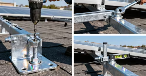
The roll forming machine determines the basic geometry of long photovoltaic profiles.
A suitable system should control:
- Alineación de la tira
- Progressive deformation
- Roller gaps
- Bend sequence
- Springback
- Simetría del perfil
- Rectitud
- Cutting coordination
Factories producing different bracket profiles can compare the machine requirements in Máquina formadora de rollos de soportes de montaje solar: perfiles C vs U.
More Roller Stations Do Not Automatically Mean Better Quality
The forming sequence matters more than the number of stations alone.
Too few stations can create severe deformation and coating stress. Too many unnecessary stations increase setup complexity and machine length.
The roller design should be based on:
- Actual profile
- Material properties
- Rango de espesor
- Required angles
- Condición de la superficie
- Velocidad de producción
- Tolerancias
Adjustable Tooling Needs Repeatable References
When one machine produces several profile sizes, adjustment systems should have measurable reference positions.
Possible methods include:
- Calibrated spacers
- Position scales
- Motorized screws
- Servo axes
- Stored recipes
- Replaceable cassettes
Every changeover should be followed by first-article inspection and an assembly fit test where required.
How Punching Equipment Influences Assembly
The punching system determines whether mounting holes and slots appear at the required positions.
A complete evaluation should include:
- Precisión de servoalimentación
- Encoder calibration
- Limpieza de herramientas
- Station arrangement
- Eliminación de babosas
- Tiempo de cambio
- Full-length pattern accuracy
- Cutting synchronization
El artículo 7 controles antes de agregar una punzonadora automática a una línea fotovoltaica provides a more detailed equipment-integration checklist. Update this internal link to the final published URL when available.
Assembly-Focused Quality Plan
A practical quality plan can divide characteristics according to their effect on installation.
| Control level | Example characteristics | Recommended control |
|---|---|---|
| Crítico | Structural connection features | Drawing-based inspection and traceability |
| Assembly-critical | Hole position, channel opening, cut length | First article plus scheduled in-process checks |
| Process-critical | Strip alignment, feeder calibration, roller gap | Setup verification and machine monitoring |
| Surface-critical | Scratches, coating damage, burrs | Visual standard and contact-surface inspection |
| General | Non-functional appearance variation | Defined sampling and acceptance criteria |
The exact classification should be agreed by the product engineering and quality teams.
Common Reasons Brackets Are Difficult to Assemble
Hole Patterns Use the Wrong Datum
The hole dimensions may be individually correct but measured from a different reference than the mating component.
Profile Opening Changes Along the Length
Roller gaps, material thickness or springback may cause the opening to vary.
Straightness Is Checked Only at the Ends
A profile can meet end measurements while curving through the middle.
Twist Is Not Included in Inspection
The rail appears straight from the side but rotates along its length.
Cut Length and Punching Are Not Synchronized
The last hole appears at the wrong distance from the cut end.
Connectors Are Not Included in First-Article Approval
Dimensional inspection passes, but the actual nut or connector does not fit.
Tool Wear Is Detected Too Late
Burrs and hole dimensions gradually deteriorate during a long production batch.
Information Needed Before Designing the Production Line
Manufacturers should provide the equipment supplier with:
- All bracket drawings
- Mating component drawings
- Especificaciones de materiales
- Rango de espesor
- Coating requirements
- Rango de longitud del producto
- Hole and slot details
- Tolerancias dimensionales
- Straightness requirement
- Twist requirement
- Expected batch sizes
- Frecuencia de cambio
- Target output
- Assembly samples
- Inspection standards
- Diseño de fábrica
This information allows the forming, punching and cutting systems to be evaluated as one production process.
Jinbolida’s existing PV Panel Brackets Production Line Guide provides additional information about the equipment stages used in modern bracket manufacturing.
Conclusión
PV panel mounting brackets become easier to assemble when every important dimension is controlled according to its function in the complete mounting system.
Cross-sectional dimensions determine connector fit. Hole and slot positions control fastener alignment. Straightness and twist affect whether long profiles can be installed without force. Cut length determines the relationship between profile ends and punched features. Burr and coating control support safe handling and finished-product quality.
The production line should therefore be designed from the completed assembly backward. Roll forming, servo feeding, punching, cutting, inspection and traceability must work together.
Suministros Jinbolida equipos fotovoltaicos de formación de soportes, multi-station punching systems and automated production-line solutions. Manufacturers can submit bracket drawings, material data, assembly requirements and output targets through the Página de contacto de Jinbolida for a customized production evaluation.
Preguntas frecuentes
Which dimensions matter most for PV panel mounting brackets?
The most important dimensions are those that affect connections: channel opening, web and flange dimensions, bend angles, hole and slot positions, cut length, straightness and twist. The exact priorities depend on the mounting-system design. Manufacturers should identify assembly-critical dimensions with the product engineer before production.
Why do mounting-bracket holes fail to align during installation?
Misalignment can result from servo-feeding error, cumulative pitch error, incorrect drawing datums, strip movement, tool wear or poor synchronization between punching and cutting. The inspection method should measure the complete hole pattern from the agreed functional reference, not only the spacing between two nearby holes.
How does profile twist affect solar-bracket assembly?
Twist rotates the profile along its length, causing mounting surfaces and holes at opposite ends to face different directions. Installers may need to force the rail into position, increasing work and introducing stress. Twist should be measured over a specified length using agreed reference surfaces rather than judged only by appearance.
Are elongated slots enough to compensate for manufacturing variation?
Slots can provide controlled adjustment when included in the engineered connection, but they should not be used to conceal uncontrolled manufacturing errors. Slot length, width, orientation and edge distance must follow the drawing. Excessive variation can still affect fastener seating, connection geometry and structural performance.
How should a factory verify that brackets are easy to assemble?
The factory should combine dimensional inspection with a functional fit test using representative connectors, nuts, bolts, clamps or splice parts. Check first articles after setup and repeat key measurements during production. A controlled assembly fixture can identify compatibility problems before a complete batch reaches installation.
 Spanish
  English
  Arabic
  Russian
  French