
Sheet Metal Punch Accuracy: A Practical Hole-Position Guide
Table of Contents
Sheet metal punch accuracy is not determined by the punching die alone. A hole can have the correct diameter and a clean edge yet still be rejected because its center position, pitch, edge distance, or relationship with other holes falls outside the drawing tolerance.
This is particularly important for solar mounting brackets, cable trays, electrical enclosures, shelving components, automotive parts, and other products that rely on multiple holes for assembly. A small error in one hole may be acceptable, but repeated pitch errors across a long profile can prevent bolts, connectors, or installation fixtures from aligning correctly.
For manufacturers planning a new sheet metal punch line or troubleshooting an existing process, this guide explains:
- How to define practical sheet metal punch accuracy
- Why feeder accuracy is not equal to finished-part accuracy
- How datum selection influences hole-position measurement
- How strip flatness, die clearance, and tool condition affect results
- How cumulative pitch error develops
- Which inspection methods are suitable for different tolerances
- How to reduce variation in production rather than only correcting individual parts
What Does Sheet Metal Punch Accuracy Actually Mean?
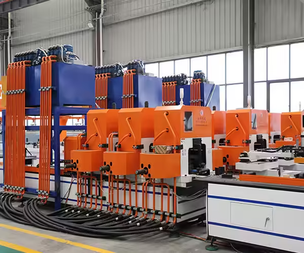
In production, sheet metal punch accuracy should be evaluated as a group of related characteristics rather than as one machine specification.
| Accuracy characteristic | What is measured | Typical production consequence |
|---|---|---|
| Hole diameter | Actual hole size after punching | Bolts or fasteners may not fit |
| Hole position | Distance from the hole center to the selected datum | Assembly holes do not align |
| Hole pitch | Center-to-center distance between adjacent holes | Progressive mismatch across the part |
| Edge distance | Hole center or edge relative to the material edge | Weak edge, tearing, or installation interference |
| Pattern orientation | Angle of a hole pattern relative to the part | Connector or bracket sits at an angle |
| Burr height | Raised material around the sheared edge | Poor fit, injury risk, coating defects |
| Hole deformation | Roundness, taper, rollover, or distortion | Reduced fastening accuracy |
| Repeatability | Variation among consecutively produced parts | Unstable batch quality |
| Long-part cumulative error | Difference between the first and last hole positions | Final mounting points fail to align |
A supplier may publish a feeder positioning accuracy, but that figure describes only one part of the system. Finished sheet metal punch accuracy is affected by the material, straightener, feeder, press, tooling, guides, control logic, downstream forming, and inspection method.
Therefore, buyers should avoid comparing machines using a single accuracy number without first confirming:
- What feature was measured?
- Which datum was used?
- What material and thickness were tested?
- How long was the test part?
- Was the tolerance measured before or after forming?
- Does the result include cumulative error?
- Was the measurement taken under actual production speed?
Start with the Finished Part and Its Assembly Function
The most reliable way to specify sheet metal punch accuracy is to begin with the part’s function.
For example, a solar mounting profile may contain a repeated series of slots for installation adjustment, several round holes for connectors, and end holes for joining adjacent profiles. These features do not necessarily require the same tolerance.
A practical tolerance strategy may classify features into three groups:
- Assembly-critical features
Holes that locate connectors, end joints, or structural interfaces usually require tighter positional control. - Function-related repeated features
Repeated slots may permit more individual variation, but the pitch and total pattern length still need control. - Non-critical features
Drainage, identification, or clearance holes may accept wider tolerances if they do not affect installation.
Applying tight tolerances to every feature can increase tooling, inspection, and production costs without improving the final product. Applying loose tolerances everywhere, however, can create expensive field assembly problems.
The drawing should identify the functional datums and use them consistently during process design, tooling manufacture, and inspection.
Datum Selection Is the Foundation of Hole-Position Control
A datum is the reference from which a dimension is established. In sheet metal punch production, common datums include:
- The leading cut edge
- A side edge of the strip
- The longitudinal centerline
- A formed flange
- A dedicated locating hole
- A finished end surface
- A combination of primary, secondary, and tertiary surfaces
If the drawing measures a hole from the finished end of a bracket, but the production line controls the hole from the incoming coil position, the process must also account for cutting accuracy and any material movement between punching and cutting.
Similarly, when a flat strip is punched before roll forming, the hole may be located correctly on the flat blank but shift relative to the finished flange after forming. This does not always mean the punching station is inaccurate. It may indicate that the flat-pattern allowance, roll-forming setup, or measurement datum is inconsistent.
For components produced on a combined punching and roll-forming line, the engineering team should agree on three questions:
- Is the tolerance applied to the flat strip or the finished profile?
- Which finished surfaces establish the inspection datum?
- Can downstream forming alter the measured hole position?
The Solar Photovoltaic Bracket Forming Machine category provides examples of equipment used to convert punched strip into finished mounting profiles. When punching and forming are connected, both processes should be evaluated as one dimensional system.
Why Servo Feeder Accuracy Does Not Guarantee Hole Accuracy
A servo feeder advances the strip by a programmed distance before each punching cycle. Its repeatability is important, but the feed command is not the same as actual material movement.
The effective feed distance can be influenced by:
- Roll pressure
- Material thickness variation
- Oil or contamination on the strip
- Surface coating
- Sudden acceleration and deceleration
- Strip tension between machines
- Material springback
- Improper straightener settings
- Misaligned strip guides
- Excessive punch withdrawal force
- Encoder installation and calibration
For example, the controller may command a 50 mm feed. The feeder rollers may rotate by the correct amount, but the strip can slip slightly because the roll pressure is insufficient. The machine believes that the feed is complete even though the material has not reached the intended position.
A more reliable sheet metal punch process checks not only the servo motion but also the relationship between the feeder, material, and punching station.
Questions to Ask When Evaluating a Feeder
- Is position feedback taken from the motor or from actual material travel?
- Can roll pressure be adjusted for different materials?
- How is feeder slip detected?
- Does the control system support feed-length compensation?
- How is the strip released or piloted before punching?
- Can different feed programs be stored by product code?
- Is the feeder sized for the strip width, thickness, and acceleration?
- What happens after an emergency stop or material splice?
These details are especially important for an automatic punching machine producing multiple hole patterns from coil material.
Cumulative Error Across Repeated Hole Patterns
One of the most common misunderstandings in sheet metal punch production is the difference between individual pitch error and cumulative pattern error.
Assume that a product contains 20 holes at a nominal pitch of 50 mm. If each feed contains a small systematic error, the last hole can deviate substantially from the expected position even though the distance between two adjacent holes appears acceptable.
Cumulative error may be caused by:
- Incorrect feed calibration
- Consistent feeder slip
- Controller rounding
- Thermal expansion
- A programmed pitch that does not match the drawing
- Measurement from different datums
- Progressive material stretching or compression
- Repeated correction based only on the previous hole
A useful inspection should therefore include:
- First-hole position from the datum
- Several adjacent hole pitches
- Intermediate hole position from the same datum
- Last-hole position from the same datum
- Total pattern length
- Position after cutting and forming
Do not inspect only the distance between neighboring holes. A local pitch measurement may hide a growing error across the complete profile.
Absolute Positioning and Incremental Positioning
In an incremental program, each new hole position is based on the previous feed. This approach is simple, but a repeated feed deviation can accumulate.
In an absolute program, each important feature is referenced to a common zero position or recalculated from a master datum. Absolute control does not eliminate mechanical error, but it can reduce the risk of software-based accumulation and make compensation easier.
Long profiles may also benefit from reference marks, pilot features, or periodic position verification, depending on the production method and required tolerance.
How Material Flatness Affects Sheet Metal Punch Accuracy
Punch Accuracy
Coil material is rarely perfectly flat when it enters the line. It may have coil set, crossbow, edge wave, center buckle, or residual stress.
If the strip is not properly leveled:
- It may not sit consistently on the die surface.
- The effective feed length can change as the strip rises and falls.
- Side guides may contact the strip unevenly.
- The punch can pull the material during withdrawal.
- Hole position may appear different after the material relaxes.
- Roll forming can release residual stress and alter the finished geometry.
A straightener must be adjusted for the actual material grade and thickness. Excessive straightening can introduce new stress, while insufficient straightening leaves the original coil curvature in the strip.
For thin or coated material, guide and roll pressure should also be controlled to avoid surface marks.
Flatness Problems Often Mistaken for Feeder Problems
If hole position changes gradually during a coil but feeder diagnostics remain stable, inspect the incoming material. A different section of the same coil can have different curvature or residual stress.
Useful checks include:
- Measuring strip flatness before the feeder
- Comparing the beginning, middle, and end of the coil
- Recording material batch and supplier
- Checking whether the error changes with strip width
- Inspecting straightener roll settings
- Comparing results at low and normal production speeds
Die Clearance and Its Effect on Hole Quality
Die clearance is the space between the punch cutting edge and die opening. It is normally selected according to material type, thickness, strength, and the desired cut quality.
Clearance primarily affects:
- Punching force
- Edge rollover
- Burnished zone
- Fracture zone
- Burr height
- Tool wear
- Slug behavior
- Hole distortion
Incorrect clearance does not necessarily move the programmed hole center by itself. However, it can indirectly reduce sheet metal punch accuracy when combined with tool misalignment, uneven cutting forces, excessive stripping force, or material movement.
| Clearance condition | Possible result |
|---|---|
| Too small | High punching force, rapid wear, secondary shearing, punch breakage risk |
| Too large | Large burr, tapered edge, distortion, poor hole definition |
| Uneven around the punch | Asymmetric edge, side force, accelerated wear, inconsistent hole shape |
| Correct and uniform | More stable cutting force, predictable edge quality, longer tool life |
The clearance should be checked around the full punch perimeter. A correct nominal clearance is not sufficient if the punch and die are not concentric.
Tool Alignment, Wear, and Punch Withdrawal
A worn punch changes more than the appearance of the hole. As the cutting edge becomes rounded, punching force and burr height increase. Material may also cling more strongly to the punch during withdrawal.
This can cause:
- Strip lifting
- Part movement
- Slug pulling
- Scratches around the hole
- Irregular hole shape
- Increased load on the feeder and guides
- Inconsistent subsequent hole positions
A suitable stripper should hold the material securely while the punch retracts. If the stripper force is too low, the strip may lift. If it is excessive or uneven, it can deform thin material or introduce friction.
Preventive tooling records should include:
- Number of strokes
- Material grade and thickness
- Burr trend
- Punch diameter
- Die condition
- Sharpening history
- Tool alignment observations
- Slug-removal performance
Tool maintenance based only on a fixed stroke count may be insufficient because wear rates vary significantly by material and process condition.
Side-to-Side Hole-Position Error
Not all sheet metal punch errors occur in the feed direction. Lateral movement can change the distance between the hole and strip edge.
Common causes include:
- Guide clearance that is too large
- Unequal guide pressure
- Variable strip width
- Slitting camber
- Misalignment between the straightener, feeder, and die
- Material rubbing against one side of the guide
- Incorrect centerline setup
- Loose tooling components
The line should be aligned along a consistent material centerline. For wide strip or long profiles, small angular misalignment can create a noticeable lateral error farther downstream.
If the left edge distance increases while the right edge distance decreases, investigate lateral strip movement before changing the punching program.
Punching Before or After Roll Forming
Hole-position strategy also depends on where punching occurs in the production sequence.
The article Solar Bracket Punching Machine: Inline vs. Separate Systems explains the broader differences between integrated and independent punching configurations.
For dimensional planning, the main comparison is:
| Process arrangement | Accuracy consideration |
|---|---|
| Punch flat strip before forming | Easy material support and tool access, but forming may change the finished hole relationship |
| Punch during an inline forming process | High automation potential, but synchronization and strip tension require control |
| Punch finished profiles | Holes can reference formed surfaces, but tooling access and profile support are more complex |
| Punch separate blanks | Flexible for multiple products, but loading and locating errors may increase |
There is no universally best arrangement. The correct choice depends on part length, hole pattern, production volume, tolerance, profile geometry, and changeover requirements.
For small connector components, a dedicated system such as the Solar Photovoltaic Bracket Connector Punching Machine can combine punching, forming, and cutting around a defined component family.
Measuring Sheet Metal Punch Accuracy
Measurement equipment should match the characteristic being inspected. A digital caliper may be sufficient for a rough pitch check, but it is often unsuitable for verifying a tight positional tolerance across a complex pattern.
The NIST dimensional metrology resources provide broader information on dimensional measurement and traceability.
Common Inspection Methods
| Inspection method | Suitable use | Main limitation |
|---|---|---|
| Steel rule or tape | Quick check of long overall distances | Low precision and operator dependence |
| Digital caliper | Hole diameter, short pitch, edge distance | Limited reach and center-location uncertainty |
| Height gauge and surface plate | Datum-based position checks | Slower and requires suitable part support |
| Optical measurement system | Hole shape, diameter, and 2D position | Field of view and part-size limitations |
| Coordinate measuring machine | Complex datum and positional inspection | Higher cost and longer inspection time |
| Go/no-go fixture | Fast production verification | Provides limited numerical data |
| Vision camera | Automated inline checks | Requires calibration, lighting, and stable presentation |
| Laser measurement | Long-part or non-contact inspection | Application-specific setup and validation |
Measure the Hole Center Correctly
Measuring from the edge of one hole to the edge of another can produce misleading results, especially when burrs or diameter variation are present.
For equal-diameter holes, some edge measurements can approximate center distance, but datum-based inspection should ideally calculate or locate the true hole center.
Burr direction also matters. If a caliper contacts the burr rather than the functional surface, the recorded position or diameter may not represent the assembled part.
Build a Practical Inspection Plan
A robust sheet metal punch inspection plan can be divided into four stages.
1. Incoming Material Inspection
Check:
- Thickness
- Width
- Material grade
- Flatness
- Surface condition
- Coil identification
2. First-Article Inspection
Before continuous production, verify:
- Datum surfaces
- First and last hole positions
- Critical pitch dimensions
- Hole diameter and shape
- Edge distance
- Burr height
- Cut length
- Dimensions after forming
3. In-Process Inspection
Use an inspection frequency based on production risk, tool wear, material variation, and historical process stability.
Track actual measurements rather than recording only “pass” or “fail.” Numerical data reveals gradual drift before parts exceed tolerance.
4. Final Batch Verification
Confirm:
- Quantity and product code
- Critical dimensions
- Complete hole pattern
- Surface and burr condition
- Part length
- Assembly fit where applicable
- Traceability to material and tooling records
Troubleshooting Common Hole-Position Problems
| Observed problem | Likely causes | Initial checks |
|---|---|---|
| Every hole is shifted by a similar amount | Incorrect datum, zero position, or program offset | Confirm drawing datum and machine zero |
| Error increases toward the last hole | Feed calibration, slip, or incremental accumulation | Measure total pattern length and actual material travel |
| Error appears randomly | Strip slip, loose tooling, unstable material, encoder issue | Check roll pressure, clamps, guides, and feedback |
| Hole position changes across strip width | Side-guide movement, camber, line misalignment | Inspect strip centerline and guide clearance |
| Hole position is correct before forming but wrong afterward | Forming deformation or wrong flat pattern | Measure before and after roll forming |
| Burr increases while position becomes unstable | Tool wear, uneven clearance, stripping problem | Inspect punch edge, die alignment, and stripper |
| First part after restart is incorrect | Lost reference, strip relaxation, improper restart logic | Review homing and restart sequence |
| Accuracy deteriorates at high speed | Insufficient settling time, vibration, strip dynamics | Compare results at several production speeds |
A disciplined troubleshooting sequence should change one condition at a time. Adjusting feeder compensation, guide position, straightener pressure, and die settings simultaneously makes it difficult to identify the real cause.
Process Capability and Measurement Reliability
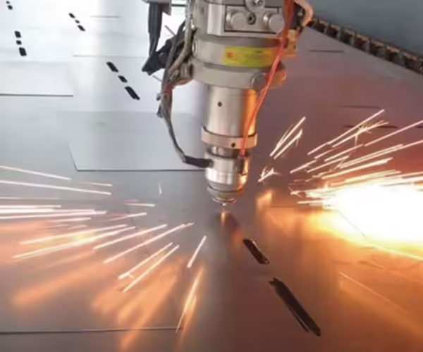
A production line should not merely make one acceptable sample. It should repeatedly produce parts within specification under expected material and speed conditions.
Before calculating process capability, confirm that the measurement system is reliable. If different inspectors obtain significantly different results from the same part, the collected production data cannot accurately describe the process.
Useful control data may include:
- Hole-position average
- Range or standard deviation
- First-to-last hole error
- Burr-height trend
- Tool stroke count
- Material batch
- Production speed
- Feeder correction history
This information helps distinguish random variation from systematic drift.
What to Confirm During Machine Acceptance
A factory acceptance test should use representative production material and actual part drawings whenever possible.
The test should confirm:
- Material grade and thickness range
- Full-length hole pattern
- Critical datum relationships
- First and last hole positions
- Repeatability across multiple parts
- Performance at agreed production speed
- Accuracy after normal stops and restarts
- Tool-change and recipe-change procedures
- Scrap and slug removal
- Finished dimensions after downstream forming
- Availability of measurement records
Testing only a short strip at reduced speed may not reveal cumulative feed error, strip instability, or production-speed vibration.
Manufacturers evaluating equipment for solar mounting components can review JBL’s rack punching equipment range and provide part drawings, material details, production targets, and tolerance requirements through the contact page.
Safety Considerations in Accuracy Adjustment
Punching equipment contains high-force moving components. Accuracy checks should never require an operator to place hands near a moving punch, feeder, or unguarded drive.
Machine guarding, interlocks, safe setup procedures, and controlled maintenance access should be incorporated into the equipment design. The OSHA machine guarding guidance offers a useful general reference for machinery safety requirements.
Tool alignment, sensor adjustment, and jam removal should be performed according to the equipment supplier’s instructions and the applicable workplace safety procedures.
Conclusion
Reliable sheet metal punch accuracy comes from controlling the entire production system: drawing datums, incoming material, straightening, feeding, strip guidance, punching tools, cutting, forming, and measurement.
The most important practical lesson is that a precise servo feeder cannot compensate for unstable material, incorrect datums, worn tooling, or inconsistent inspection. Likewise, a clean hole does not prove that the full hole pattern is positioned correctly.
For long profiles and repeated patterns, always inspect the first hole, intermediate positions, the final hole, and the total pattern length from a common datum. Measurements should also be repeated after forming when the finished profile—not the flat strip—is the functional product.
By defining accuracy according to assembly needs and validating it under real production conditions, manufacturers can reduce rework, improve installation consistency, and select a sheet metal punch system based on measurable performance rather than a single catalogue specification.
Frequently Asked Questions
1. What determines sheet metal punch accuracy?
Sheet metal punch accuracy is determined by the combined performance of the feeder, straightener, guides, press, punch-and-die set, stripper, control system, material, and inspection method. Tooling accuracy alone is insufficient because strip slip, flatness, datum selection, and downstream forming can all change the finished hole position.
2. Why does hole-position error increase along a long part?
An increasing error usually indicates feed calibration deviation, repeated strip slip, incremental programming, or material movement. Even a small systematic error in every feed can accumulate across many holes. Measure each important hole from one fixed datum, including the first and last holes, instead of checking only adjacent pitch.
3. Does die clearance affect hole position?
Die clearance mainly affects punching force, burr height, edge quality, tool life, and hole distortion. It may indirectly affect hole-position consistency if clearance is uneven, tooling is misaligned, or excessive punching and withdrawal forces move the strip. Uniform clearance and correct punch-to-die alignment are both essential.
4. Should holes be measured before or after roll forming?
If the drawing tolerance relates to final assembly, holes should be verified on the finished formed profile. Measuring the flat strip is still useful for controlling the punching process, but roll forming can change the hole’s relationship to flanges, edges, and finished datums. Ideally, critical features are checked at both stages.
5. How can cumulative hole-pitch error be reduced?
Start by calibrating actual material travel, maintaining stable feeder pressure, controlling strip flatness, aligning guides, and referencing important positions to a common datum. Inspect total pattern length and the last-hole position regularly. Absolute positioning, reference features, and validated compensation can further reduce systematic accumulation.
 English
  Arabic
  Russian
  Spanish
  French