
Solar Bracket Punching Machine: Inline vs Separate Systems
Table of Contents
A solar bracket punching machine produces the holes, slots, notches, and connection features required for photovoltaic mounting profiles. Although punching may appear to be a simple production step, it directly affects installation speed, component interchangeability, structural connections, and finished-bracket quality.
Buyers generally choose between an inline punching system integrated with a roll forming machine and a separate punching machine operated as an independent process. Each configuration has advantages, limitations, and suitable production scenarios.
Key takeaways:
- Inline punching reduces material handling and can improve continuous production.
- Separate punching systems provide greater flexibility for varied or low-volume parts.
- Pre-punching is usually performed while the strip is flat.
- Post-punching can position holes relative to the finished profile.
- Punching capacity must be calculated from material strength, thickness, and total cutting perimeter.
- Servo feeding accuracy is essential for controlling hole spacing and end distance.
- Maximum punching speed does not always equal qualified production output.
- Punching dies should be designed from approved product drawings.
- Factory acceptance testing should include different hole patterns and material thicknesses.
What Is a Solar Bracket Punching Machine?
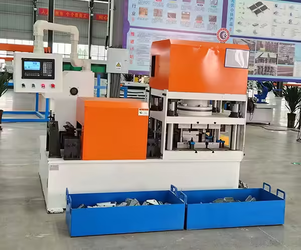
A solar bracket punching machine is designed to create installation and connection features in metal components used for photovoltaic mounting systems. These features may include round holes, elongated slots, square holes, notches, embossing, and customized patterns.
The machine may process flat strip, individual blanks, or finished C-, U-, and Z-shaped profiles. Its configuration depends on where punching occurs within the complete production process.
Main Function of the Equipment
The primary function is to create repeatable holes at defined positions. Accurate punching allows brackets, rails, connectors, clamps, and fasteners to align correctly during installation.
The machine must control more than hole size. It must also maintain spacing, orientation, edge distance, and the relationship between holes and finished profile length.
Typical Materials
Solar mounting components are commonly manufactured from galvanized steel, pre-coated steel, stainless steel, aluminum, or specified high-strength materials.
Material grade, tensile strength, coating, and thickness influence the required press capacity, die clearance, punching speed, and tool material.
Common Products
A solar bracket punching machine may be used to manufacture:
- C-channel mounting rails
- U-channel supports
- Z-shaped purlins
- Solar strut channels
- Pile and post components
- Rail connectors
- Base plates
- Bracing components
- Clamps and fixing plates
- Customized mounting accessories
Inline vs Separate Solar Bracket Punching Systems
The main difference is whether the punching operation is integrated into a continuous production line or completed on an independent machine.
The correct choice depends on product variety, order volume, factory layout, automation goals, and required production flexibility.
| Comparison factor | Inline punching system | Separate punching system |
|---|---|---|
| Production flow | Connected with feeding and roll forming | Independent processing step |
| Material handling | Relatively low | Requires loading and unloading |
| Best order type | Repeated, high-volume profiles | Varied products and smaller batches |
| Hole programming | Coordinated with line controls | Controlled independently |
| Production speed | Depends on the complete line cycle | Depends on individual machine cycle |
| Changeover flexibility | Optimized for defined profile families | Can process several compatible parts |
| Labor requirement | Usually lower | May require additional operators |
| Factory layout | Requires an organized linear layout | Can be positioned as a separate work center |
| Main risk | One fault may stop the complete line | Additional handling may reduce efficiency |
Neither system is automatically better. The correct configuration should reflect how the factory receives orders and organizes production.
How Does an Inline Punching System Work?
An inline system connects the solar bracket punching machine with an uncoiler, leveling unit, servo feeder, roll forming machine, cutting system, and product collection table.
The strip moves through a coordinated process controlled by a central PLC.
Coil Feeding
The metal coil is loaded onto an uncoiler and fed into the production line. A leveling device prepares the strip before it reaches the punching section.
Stable feeding helps prevent errors caused by strip movement, coil tension, or uneven material.
Servo Positioning
The servo feeder advances the strip by a programmed distance. Once the target position is reached, the punching press creates the required holes or slots.
Different feeding programs can be stored for different product lengths and hole layouts.
Roll Forming
After punching, the flat strip enters the forming stations and is gradually shaped into a solar mounting profile.
The control system must account for the relationship between the hole position, forming process, and final cutting point.
Length Cutting
The formed profile is cut according to the programmed product length. Punching and cutting must use the same reference logic to maintain the required distance between the last hole and the profile end.
Integrated Production Control
A properly integrated system coordinates feeding, punching, forming, and cutting. If these processes operate independently without accurate communication, hole patterns may gradually move away from their intended positions.
How Does a Separate Punching System Work?
A separate solar bracket punching machine operates independently from the roll forming line. It may process flat blanks, coil strip, or previously formed components.
This configuration can be useful when a factory produces many different parts or when punching cycles do not match the speed of the main forming line.
Flat Blank Punching
Metal sheets or cut blanks are positioned inside the press and punched before entering another production process.
This method may suit base plates, connectors, clamps, or low-volume customized components.
Coil-Fed Punching
A separate coil-fed line can include an uncoiler, leveling unit, servo feeder, press, and cutting system. The punched strip may then be stored or transferred to a forming line.
This creates an additional production stage but allows punching and roll forming to operate on different schedules.
Finished-Profile Punching
Some machines punch holes after the C-, U-, or Z-shaped profile has already been formed. Customized support dies are usually required to prevent deformation.
When Separate Processing Makes Sense
A separate system can be practical when one punching machine serves several forming lines or processes products that are not suitable for one continuous line.
Pre-Punching vs Post-Punching
Punching can occur before or after the bracket is formed. The decision affects tooling access, hole positioning, line speed, and the risk of profile deformation.
Pre-Punching Flat Strip
Pre-punching creates holes while the metal remains flat. The strip is easier to support, and both sides of the material are accessible to the die.
This is commonly used for solar mounting channels containing repeated slots.
Advantages of Pre-Punching
- Simple material support
- Convenient die access
- Suitable for several hole shapes
- Easy integration with servo feeding
- Lower risk of deforming a finished profile
- Efficient for repeated patterns
Potential Limitations
The subsequent forming process may slightly change the final relationship between holes and profile edges. Tooling design and feeding control must compensate for predictable material movement.
Post-Punching Finished Profiles
Post-punching creates holes after roll forming. It can be useful when hole locations must be referenced directly from the finished cross-section.
However, the formed profile can restrict die access and complicate material support.
Advantages of Post-Punching
- Hole location references the finished profile
- Suitable for selected flange or side holes
- Useful for some customized patterns
- Can process existing finished channels
Potential Limitations
Supporting a three-dimensional profile requires specialized tooling. Excessive punching force or poor support may crush, twist, or mark the bracket.
How to Calculate Required Punching Capacity
The rated tonnage of a solar bracket punching machine must be sufficient for the most demanding material and hole combination.
Selecting press capacity only from strip thickness can produce an inaccurate result.
Material Shear Strength
Stronger materials require more force to punch than lower-strength materials of the same thickness. The supplier should receive the actual material grade and mechanical properties.
Material Thickness
Punching force generally increases as material thickness increases. If the machine will process several thicknesses, capacity should be checked using the thickest specified material.
Total Cutting Perimeter
The cutting perimeter is the combined length of the edges being sheared during one press stroke. Multiple holes punched simultaneously may require considerably more force than one hole.
More Holes Require More Force
A die that punches six slots in one stroke does not have the same force requirement as a die that punches one slot. The complete hole arrangement must be included in the calculation.
Safety Allowance
The press should have a reasonable capacity allowance rather than operating continuously at its absolute limit. The supplier should explain the calculation and recommended working range.
Common Hole Types in Solar Brackets
Photovoltaic mounting components use different hole shapes depending on their assembly method.
The punching die must reproduce these features consistently throughout long production runs.
Round Holes
Round holes are commonly used for bolts, screws, pins, and fixed connections. Important dimensions include diameter, spacing, and distance from the profile edge.
Elongated Slots
Slots allow a limited amount of installation adjustment. Their width, length, end radius, and orientation should follow the approved drawing.
Square or Rectangular Holes
These holes may be used with specialized bolts or connection systems. Their corners and dimensions must be controlled carefully.
Notches
Notches remove material from an edge or corner to support bending, assembly, or clearance requirements.
Embossed Features
Embossing creates a raised or recessed feature rather than removing material. It may be used for strengthening, positioning, identification, or connection purposes.
Combined Punching Operations
A single die set may complete several holes, slots, notches, or embossed features in one stroke. This can improve efficiency but increases tooling complexity and press-force requirements.
Servo Feeding and Hole Position Accuracy
Accurate punching depends on both the press and the feeding system. Even a high-quality die cannot produce correct hole spacing if the material is positioned inaccurately.
A servo feeder uses programmed movement to advance the strip by controlled distances.
Feeding Accuracy
Feeding accuracy affects the distance between consecutive holes. Errors may accumulate along long profiles if the control system does not position the strip consistently.
Material Slippage
Oil, coating condition, incorrect roller pressure, and strip tension may cause the material to slip during feeding.
The feeding system should hold the strip securely without damaging its protective surface.
End-Distance Accuracy
The distance from the first and last holes to the cut ends is important for assembly. Punching and cutting controls must share a consistent product-length reference.
Program Management
When many bracket specifications are produced, saved programs can reduce manual data entry. Access control and parameter verification help prevent operators from selecting the wrong hole pattern.
Stop Punching vs Flying Punching
The punching motion can be completed while the material is stationary or while it continues moving.
This choice influences line design, output, control complexity, and investment cost.
Stop-to-Punch System
The feeder advances the strip, stops at the correct position, completes the punching stroke, and then continues feeding.
This system is relatively straightforward and can support complex hole patterns. However, frequent stops may limit total line speed.
Flying Punching System
A flying system moves with the strip during punching. The material does not need to stop for every cycle.
Flying punching can support higher continuous production, but it requires synchronized motion control and a suitable die arrangement.
Which System Should You Choose?
Choose according to actual order volume, hole frequency, profile length, accuracy requirements, and expected production speed.
A high-speed flying system may not provide a meaningful return when the factory mainly produces small customized batches.
How Punching Affects the Roll Forming Process
Punching removes material and changes local strip stiffness. Closely spaced slots or large openings can make the strip more sensitive during roll forming.
The forming tooling should guide the perforated material without distorting the holes.
Hole Deformation
Holes located near a bend may become elongated or distorted during forming. The product designer and machine supplier should review the distance between holes and bend lines.
Strip Strength
A dense punching pattern can weaken the flat strip before it enters the forming stations. Proper guides may be required to prevent buckling or unstable feeding.
Burr Direction
Punching creates a burr on one side of the material. Burr direction may influence forming, coating condition, assembly, and operator safety.
Confirm Orientation Before Tooling Design
The supplier must know which surface becomes the inside or outside of the finished channel. Reversing the strip orientation later may place holes or burrs on the wrong side.
Punching Die Selection
The die is one of the most important components of a solar bracket punching machine. Its design affects hole accuracy, edge quality, tool life, changeover time, and maintenance cost.
Single-Pattern Dies
A single-pattern die is optimized for a defined hole arrangement. It can be stable and efficient for high-volume production of one bracket type.
Multi-Pattern Dies
A multi-pattern die contains several punches or stations that can be activated according to the selected program.
This configuration can improve flexibility but requires more complex controls and careful maintenance.
Quick-Change Dies
Quick-change systems reduce the time required to replace one die set with another. They are useful for factories producing several unrelated hole patterns.
Die Material
Tool material should be selected according to the bracket material, thickness, production volume, coating, and required service life.
Spare Punches and Wear Parts
Punches, dies, springs, guides, and stripping components are wear parts. The initial equipment order should include a recommended spare-parts list.
Inline vs Separate System Cost Factors
The purchase price of a solar bracket punching machine is only one part of the total investment.
Buyers should compare production flow, labor, floor space, material handling, maintenance, and future product flexibility.
| Cost factor | Inline system | Separate system |
|---|---|---|
| Initial integration | Usually higher | May be lower for a basic press |
| Material transfer | Limited | Additional handling required |
| Labor | Lower in an automated line | May require separate operators |
| Floor space | Long continuous layout | Flexible but may need buffer areas |
| Downtime impact | Punching fault can stop the full line | Other lines may continue operating |
| Product flexibility | Best within its designed profile family | Can serve several compatible products |
| Work-in-progress inventory | Usually lower | Punched material may require storage |
| Control complexity | Higher coordination requirement | Independent and relatively simpler |
A total-cost comparison should use expected annual production and product variety rather than focusing only on the equipment quotation.
How to Choose the Right Solar Bracket Punching Machine
Before requesting a quotation, prepare complete product and production information.
This allows the supplier to calculate the press, die, feeding, control, and cutting requirements accurately.
Product Information
Provide:
- Finished bracket drawings
- Material grade
- Yield and tensile strength
- Material thickness
- Coil or blank dimensions
- Hole and slot drawings
- Hole-to-hole distances
- Hole-to-edge distances
- Finished profile length
- Required tolerances
Production Information
Explain:
- Required pieces per shift
- Main product specifications
- Average order size
- Number of daily changeovers
- Required automation level
- Future product plans
- Inspection requirements
Factory Information
Confirm:
- Available voltage and frequency
- Floor space
- Coil lifting method
- Factory crane capacity
- Material flow
- Number of operators
- Connection with existing equipment
Jinbolida’s solar photovoltaic rack punching equipment provides production options for manufacturers planning automated hole processing.
Factory Acceptance Test Checklist
The factory acceptance test should verify the machine using representative production material and approved drawings.
The test should cover accuracy, stability, output, changeover, and finished-part quality.
Inspect Hole Quality
Check:
- Hole and slot dimensions
- Position accuracy
- Edge distance
- Burr height
- Surface marks
- Deformation
- Repeated-pattern consistency
Test Different Patterns
If the machine supports several programs, test more than one hole arrangement. Confirm that stored programs produce the correct sequence.
Test the Thickest Material
Testing only thin material may not demonstrate whether the press and die can handle the maximum required load.
Verify Production Speed
The test should measure the complete working cycle. Do not calculate output from servo feeding speed alone.
Review Changeover Procedures
Ask the supplier to demonstrate die changes, program selection, adjustment, lubrication, and routine cleaning.
Common Purchasing Mistakes
Avoiding common specification errors can reduce tooling modifications and production delays.
Sending Only a Product Photo
A photo does not show exact dimensions, tolerances, material properties, or hole positions. Submit an approved technical drawing.
Ignoring Cutting Perimeter
Press force must be calculated using all holes punched in one stroke, not only the largest individual hole.
Choosing by Tonnage Alone
Accuracy, frame rigidity, feeder control, die quality, and system integration are as important as nominal press capacity.
Forgetting Coating Protection
Rough guides, dirty tooling, and excessive feeding pressure can scratch galvanized or pre-coated steel.
Assuming Every Pattern Uses One Die
Products with different hole shapes or arrangements may require separate or multi-pattern tooling.
Overestimating Production Speed
A high feeding speed does not guarantee high output when the machine must stop frequently for punching and cutting.
Conclusion
Choosing between an inline and separate solar bracket punching machine depends on product variety, production volume, automation level, factory layout, and future manufacturing plans.
Inline punching supports continuous production and reduces material handling. Separate equipment can provide greater flexibility and may serve several production lines or different component types.
Regardless of the configuration, buyers should focus on material properties, press-force calculations, servo feeding, die design, hole accuracy, coating protection, punching speed, and system integration. A complete factory acceptance test should verify the machine against approved drawings and representative production material.
Manufacturers planning a fully integrated line can review Jinbolida’s solar mounting production line and photovoltaic equipment production solutions. For equipment selection based on your bracket drawings and capacity requirements, send the project details through the contact page.
FAQ
What does a solar bracket punching machine produce?
It creates holes, slots, notches, and embossed features in rails, channels, purlins, connectors, base plates, and other photovoltaic mounting components.
Is inline punching better than separate punching?
Inline punching is suitable for continuous, high-volume production with limited material handling. Separate punching can offer greater flexibility for varied parts and smaller orders.
Should solar channels be punched before roll forming?
Pre-punching is common because flat strip is easy to support and access. However, the correct method depends on hole position, profile design, and tolerance requirements.
Can one punching machine produce different hole patterns?
Yes, when the dies and control system are designed for multiple patterns. Some changes may be programmed, while others require a die replacement.
How much press capacity is required?
Required capacity depends on material shear strength, thickness, total cutting perimeter, and the number of holes punched in one stroke.
Can galvanized steel be punched without damaging the coating?
Punching always exposes a cut edge, but suitable die clearance, clean tooling, controlled feeding, and proper material handling can reduce unnecessary surface damage.
What causes inaccurate hole spacing?
Possible causes include servo feeding errors, strip slippage, incorrect parameters, unstable coil tension, worn dies, and poor coordination between punching and cutting.
What is flying punching?
Flying punching completes the punching cycle while the material continues moving. It can improve continuous production but requires more advanced synchronization.
What information should I send to the supplier?
Send drawings, material data, thicknesses, hole patterns, tolerances, production targets, automation requirements, coil details, and factory power conditions.
How should the machine be tested before shipment?
Test representative materials and several hole patterns. Measure dimensions, spacing, edge distance, burrs, deformation, cycle speed, and repeated accuracy.
If you enjoyed this article on Jinbolida’s smart manufacturing and digital factory expertise, follow us for more insights and updates:
- 📘 Facebook: Stay tuned for our latest smart production line projects → Facebook
- 📱 WhatsApp: Contact us anytime for custom production solutions → Chat Now
- ▶️ YouTube: Watch our automated line demos and real-world applications → YouTube
Let’s keep innovating and shaping the future of smart manufacturing — together!
 English
  Arabic
  Russian
  Spanish
  French