
Formado de bobinas de acero galvanizado: cómo prevenir daños en el revestimiento
Tabla de contenido
Galvanized steel coil is widely used to produce photovoltaic brackets, construction profiles, roofing components, channels and other outdoor metal products. Its zinc coating protects the underlying steel, but that surface can be scratched, marked or contaminated as the strip passes through guides, leveling rollers, punches, forming stations and cutting equipment.
Coating damage is not always caused by poor raw material. It may originate from incorrect tooling clearance, dirty rollers, excessive guide pressure, unstable feeding, trapped metal particles or unsuitable finished-product handling.
Este artículo explica:
- Why galvanized coatings are used
- Which material information should be confirmed
- Where coating damage occurs in a production line
- How scratches, pressure marks and zinc buildup develop
- How tooling design affects the galvanized surface
- Which controls are needed during punching and cutting
- How lubrication and cleaning should be managed
- What should be included in finished-profile inspection
- How to troubleshoot repeated coating defects
The most effective way to protect galvanized steel coil is to control every surface that contacts the material. Smooth tooling, correct clearance, stable alignment, clean production paths and supported product handling are more reliable than trying to repair damaged profiles after forming.
What Is Galvanized Steel Coil?
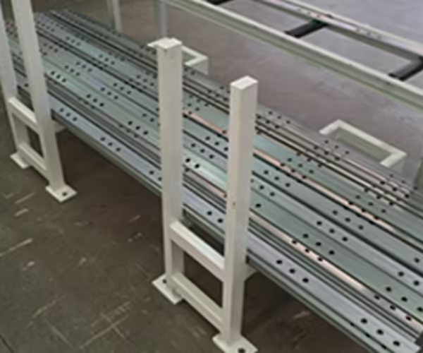
Galvanized steel coil is steel strip coated with zinc to improve corrosion protection. In continuous galvanizing, the steel strip is cleaned, coated and rewound into a coil before being supplied for subsequent manufacturing.
El hot-dip galvanization process creates a zinc-based protective coating on steel. Zinc can provide barrier protection and sacrificial protection, helping protect exposed steel when the coating remains continuous and properly applied.
Depending on the product and specification, coated coil may include:
- Zinc-coated galvanized steel
- Zinc-iron alloy-coated steel
- Zinc-aluminum-coated steel
- Zinc-aluminum-magnesium-coated steel
- Pre-painted galvanized steel
- Other metallic-coated sheet products
The exact coating system should be stated in the material specification. Referring to every coated coil simply as “galvanized steel” does not provide enough information for tooling design or quality inspection.
Why Galvanized Steel Coil Is Used for PV Brackets
Photovoltaic mounting profiles are exposed to rain, humidity, temperature variation and other outdoor conditions. Galvanized steel is commonly selected because it combines structural strength, manufacturability and corrosion protection.
Typical formed products include:
- C-channel mounting brackets
- U-channel rails
- Canales de puntal ranurados
- Correas en forma de Z
- Puestos de apoyo en tierra
- Miembros vigorizantes
- Perfiles de montaje en techo
- Connector components
Jinbolida Máquina formadora de soportes para sistemas solares fotovoltaicos range is designed for producing C-, U- and related solar mounting profiles from coil-based materials.
Confirm the Galvanized Steel Coil Specification
Tooling engineers need more than coil thickness and width. The complete material specification should be reviewed before the roll forming and punching systems are designed.
Proporcionar:
- Base steel grade
- Fuerza de rendimiento
- Resistencia a la tracción
- Alargamiento
- Nominal thickness
- Tolerancia al espesor
- Ancho de la tira
- Tolerancia al ancho de la tira
- Tipo de revestimiento
- Coating designation
- Coating mass or thickness
- Surface treatment
- Spangle or appearance requirement
- Diámetro interior de la bobina
- Diámetro exterior de la bobina
- Peso máximo de la bobina
- Protective oil or passivation
- Required finished surface condition
Base Steel Strength
Higher-strength steel usually produces more springback and greater forming resistance. This can require a different forming sequence, more rigid shafts and carefully controlled roller gaps.
If a machine is tested with soft material but later operates with higher-strength galvanized steel coil, the profile may show:
- Incorrect bend angles
- Flange variation
- Giro de perfil
- Increased roller pressure
- Marcado de superficies
- Higher drive load
The factory acceptance test should therefore use material that represents actual production conditions.
Coating Type and Surface Treatment
Different coatings do not behave identically during bending, punching or sliding contact. A surface treated with oil, passivation or protective film may require different handling from a dry, appearance-sensitive surface.
Before approving the machine configuration, clarify:
- Whether lubricant is already present
- Whether additional lubricant is permitted
- Whether the finished profile will be painted
- Whether a protective film is used
- Whether film must remain attached after forming
- Which surface defects are acceptable
- How coating damage will be measured
Where Coating Damage Occurs
Galvanized steel coil passes through several contact points. Any one of them can create a continuous scratch or repeated mark.
| Production area | Typical defect | Likely cause |
|---|---|---|
| Carga de bobinas | Edge damage or dents | Incorrect lifting or coil support |
| Desenrollador | Edge rubbing | Coil not centered |
| Unidad de nivelación | Parallel pressure marks | Excessive roller pressure or contamination |
| Entry guide | Continuous longitudinal scratch | Guide too tight or rough |
| Servorrealimentador | Repeated grip marks | Excessive clamping pressure |
| Estación de punzonado | Burrs, coating cracks or dragged marks | Incorrect clearance or worn tooling |
| Rodillos formadores | Scratches, zinc pickup or flaking | Rough surfaces, debris or excessive deformation |
| Cutting unit | Damaged cut edge or deformation | Worn cutting tool or poor support |
| Mesa agotada | Bottom-surface scratches | Rough table or trapped particles |
| Stacking area | Impact marks or white staining risk | Uncontrolled handling or wet storage |
The location and pattern of a defect often reveal where it originated.
Por ejemplo:
- One continuous scratch usually comes from a fixed guide or contaminated roller.
- Repeated marks at a consistent interval may come from one rotating tool.
- Damage only near punched holes indicates a clearance or stripping problem.
- Marks only on the bottom surface often come from receiving and stacking equipment.
Prevent Damage During Coil Loading
Surface protection starts before the coil enters the machine.
Use Suitable Coil-Handling Equipment
Coils should be lifted and transported with equipment designed for their weight, width and orientation. Incorrect fork positions, chains or lifting attachments may dent coil edges or damage outer wraps.
The loading process should prevent:
- Coil impact
- Edge contact with the floor
- Excessive compression
- Sliding across rough surfaces
- Contact with sharp lifting equipment
- Exposure to water or contaminants
Inspect the Coil Before Loading
Record any existing damage before production begins.
The incoming inspection should cover:
- Identificación de bobinas
- Condición de embalaje
- Condición del borde
- Outer-wrap damage
- Arañazos superficiales
- Water exposure
- Rust or wet-storage staining
- Coil telescoping
- Certificado de materiales
This prevents raw-material defects from being incorrectly attributed to the forming machine.
Center the Coil Correctly
A coil loaded off-center may force the strip against one side of the guides. Operators may then tighten the guide to control movement, creating continuous scratches.
The decoiler centerline, leveler centerline and forming centerline should be aligned during installation and checked after major maintenance.
Control Leveling Pressure
The leveling machine reduces coil curvature before feeding, punching and forming. It should flatten the strip without creating unnecessary surface pressure.
Excessive Leveling Pressure
When the upper and lower rollers are set too tightly, the strip may show:
- Parallel pressure lines
- Surface polishing
- Zinc smearing
- Roller-imprint patterns
- Unnecessary work hardening
- New strip distortion
The problem may become more visible on bright or appearance-sensitive galvanized material.
Insufficient Leveling
Too little leveling pressure allows coil set to remain. The strip may lift, move sideways or feed inconsistently, leading to downstream scratches and hole-position errors.
Operators should record suitable settings for each material grade and thickness. A recipe can provide a starting point, but the incoming coil condition should still be checked.
Keep Entry Guides Properly Adjusted
Entry guides should locate the strip without clamping it tightly.
A common mistake is using side guides to force an unstable strip into position. This creates friction along the strip edge or main surface.
Guides should be:
- Smooth
- Clean
- Correctly aligned
- Free from burrs
- Suitable for the coating
- Adjusted with minimal necessary clearance
- Supported so they cannot vibrate
If a strip repeatedly moves sideways, inspect the coil position, leveling and machine centerline before applying more guide pressure.
Use Replaceable Contact Surfaces
High-contact guide components may use replaceable wear surfaces where suitable for the application. The selected material should not embed hard particles or react adversely with the galvanized surface.
Wear parts should be included in routine inspection because even a small burr can create a scratch along an entire production batch.
Optimize Forming Roller Design
Forming rollers determine how gradually the strip reaches its final profile. An aggressive forming sequence can place excessive strain on the coating.
Use a Controlled Forming Sequence
Each station should perform an appropriate part of the total deformation. Attempting to complete a major bend over too few stations can create:
- Localized coating stress
- Flaking near bend lines
- Surface pressure marks
- Onda de borde
- Giro de perfil
- Excessive springback
The American Galvanizers Association notes in its galvanized steel FAQ that larger bend radii and controlled bending can help reduce the possibility of coating damage during fabrication. Although continuously galvanized sheet and after-fabrication hot-dip galvanized products are different material forms, the general principle remains useful: severe localized deformation creates greater coating stress.
Avoid Unnecessarily Small Bend Radii
The minimum suitable inside radius depends on:
- Base steel ductility
- Grosor del material
- Tipo de revestimiento
- Condición del revestimiento
- Bend direction
- Finished-product requirement
A small radius may be necessary for assembly, but it should be confirmed through testing rather than assumed from an uncoated steel drawing.
Check Roller Edge Geometry
Sharp roller transitions can concentrate pressure. Tooling edges should be designed to support the required bend without cutting, scraping or pinching the coating.
Roller profiles should also account for:
- Material thickness tolerance
- Springback
- Flange growth
- Condición del borde
- Punch locations
- Final straightening
Maintain Smooth and Clean Roller Surfaces
Even precision-machined rollers can damage galvanized steel coil when their surfaces become contaminated.
Zinc Pickup
Repeated pressure and sliding contact may transfer zinc or other residue onto a roller. The buildup changes the effective roller shape and creates raised contact points.
Possible effects include:
- Repeated surface marks
- Changing profile dimensions
- Increased friction
- Coating smearing
- Irregular strip movement
The line should be stopped and cleaned before a small buildup damages a large batch.
Embedded Metal Particles
Punching and cutting can generate slugs, burr fragments and fine metal particles. If these enter the forming stations, they can become trapped between the strip and rollers.
A single hard particle may produce a long scratch before it is detected.
Good controls include:
- Effective scrap chutes
- Covers between operations
- Magnetic or mechanical collection where appropriate
- Scheduled roller cleaning
- Clean run-out tables
- Separation of grinding work from the forming area
Roller Surface Finish
Roller surfaces should be produced and maintained according to the finished surface requirement. Roughness, machining lines, pitting and corrosion may transfer to the galvanized strip.
Damaged rollers should be repaired or replaced. Operators should not use aggressive cleaning methods that create new scratches on the tooling.
Reduce Damage During Punching
Photovoltaic profiles frequently contain round holes and elongated slots. Punching can damage the coating around these features if tooling is worn or incorrectly set.
Jinbolida Equipos de perforación de bastidores para sistemas solares fotovoltaicos includes multi-station systems for producing different photovoltaic bracket features.
Use Correct Punch-to-Die Clearance
Incorrect clearance can produce:
- Rebabas pesadas
- Tearing
- Agujeros distorsionados
- Coating cracking
- Tirar de babosas
- Excessive stripping force
- Desgaste rápido del punzón
The clearance should be matched to material strength and thickness. When one machine processes several galvanized steel coil specifications, tooling requirements should be documented for each range.
Control Slug Removal
A slug that remains attached to the punch can be pulled upward and pressed into the next section of strip. This may cause deep marks, double punching or tool damage.
Reliable slug control may require:
- Proper die relief
- Suitable punch geometry
- Vacuum or air assistance
- Scrap chutes
- Sensores
- Regular cleaning
Support the Strip
The strip should remain stable during punching. Unsupported movement can deform the area around a hole or allow the surface to rub against the tooling.
For a broader comparison of integrated punching arrangements, refer to Punzonadora de soporte solar: sistemas en línea versus sistemas separados.
Select Lubrication Carefully
Lubrication can reduce friction, forming force and zinc pickup, but it must be compatible with downstream operations and finished-product requirements.
Before introducing a lubricant, check:
- Coating compatibility
- Compatibilidad con películas protectoras
- Painting or bonding requirements
- Welding requirements
- Cleaning process
- Environmental and workplace controls
- Residue limits
- Application quantity
Excess lubricant may attract particles and contaminate rollers, while insufficient lubrication may increase friction.
A controlled application system is preferable to inconsistent manual application. The objective is to provide the necessary lubrication without flooding the strip or creating uneven residue.
Do Not Mix Lubricants Without Review
Different coil suppliers may provide material with different mill oils or surface treatments. Adding another product without compatibility testing may create staining, poor cleaning or inconsistent friction.
Record the incoming surface condition and approved lubricant for each material specification.
Protect the Coating During Cutting
Cutting creates a fresh edge and may also deform the profile if the tool is worn or unsupported.
Inspeccionar:
- Cut-end squareness
- Altura de la rebaba
- Deformación final
- Coating damage near the cut
- Desgaste de herramientas
- Profile support
- Eliminación de desechos
A cutting die should match the completed profile. If the profile is not fully supported, the cut may crush flanges or scrape the coated surface.
The receiving table should also support the product immediately after cutting. Long profiles should not drop onto metal surfaces.
Improve Finished-Profile Handling
A qualified profile can still be damaged after leaving the machine.
Run-Out Tables
Run-out tables should be:
- Clean
- Smooth
- Correctly aligned
- Long enough for the product
- Free from exposed fasteners
- Able to support the profile without sagging
Contact strips or rollers should be inspected for embedded particles.
Apilamiento automático
Automatic stacking can reduce uncontrolled impact and manual dragging. However, the stacker must suit the profile geometry and length.
Products should not collide, slide excessively or become trapped during transfer.
Jinbolida Equipos auxiliares de máquinas formadoras can be considered when a line requires improved receiving, stacking or automated material handling.
Packaging and Storage
Freshly produced profiles should be stored in a dry, ventilated condition. Water trapped between closely stacked galvanized surfaces can contribute to wet-storage staining.
El American Galvanizers Association’s corrosion-protection guidance explains how zinc surfaces develop protective corrosion products under normal wet and dry atmospheric cycles. During storage, however, prolonged trapped moisture should be avoided.
Los controles útiles incluyen:
- Dry storage
- Ventilated stacking
- Separation from wet floors
- Protection from condensation
- Suitable packaging
- Drainage paths
- Clear batch identification
Inspect Galvanized Profiles Systematically
Surface inspection should use defined lighting, viewing distance and acceptance criteria.
Incoming Inspection
Check the coil before production for existing scratches, coating irregularities, edge damage and wet-storage staining.
Inspección del primer artículo
After setup, examine:
- Both main surfaces
- Profile edges
- Bend lines
- Punched holes
- Cut ends
- Guide-contact areas
- Roller-contact areas
- Stacking-contact areas
Inspección en proceso
Inspect at defined intervals and after:
- Cambios de bobina
- Ajustes de herramientas
- Punch or die replacement
- Limpieza
- Line stops
- Cambios
- Unusual alarms
Defect Sample Board
A defect sample board helps operators distinguish acceptable appearance variation from processing damage.
It can include examples of:
- Light pressure marks
- Rejectable scratches
- Zinc pickup
- Burr-related damage
- Grietas en el revestimiento
- Handling dents
- Wet-storage staining
- Raw-material defects
Acceptance criteria should be agreed between the component manufacturer and its customer.
Troubleshooting Galvanized Steel Coil Defects
| Defect pattern | Probable source | First inspection |
|---|---|---|
| Continuous straight scratch | Fixed guide or trapped debris | Entry and exit guides |
| Repeated mark at equal spacing | Rotating roller defect | Roller circumference |
| Marks across full width | Leveling pressure or dirty roller | Unidad de nivelación |
| Damage around holes | Punch clearance or worn tool | Punch and die |
| Scratches on bottom only | Receiving table or conveyor | Run-out area |
| Flaking at bend line | Severe bend or coating condition | Forming sequence and material |
| Zinc buildup on rollers | Friction, pressure or contamination | High-load forming stations |
| Edge rubbing | Poor coil centering | Decoiler and guides |
| Random short scratches | Loose particles | Entire material path |
| White surface deposits | Trapped moisture | Packaging and storage |
Stop Before the Defect Spreads
When a repeated scratch appears, continuing production may convert one tooling problem into an entire rejected coil.
A useful response is:
- Stop the line safely.
- Mark the last known acceptable product.
- Identify the defect direction and spacing.
- Inspect the corresponding contact point.
- Clean or correct the source.
- Produce a new first article.
- Confirm the correction before restarting the batch.
Avoid adjusting several stations simultaneously because this makes the original cause more difficult to identify.
Factory Acceptance Testing with Galvanized Steel Coil
A forming line intended for coated steel should be tested with the agreed coating and material strength.
The factory acceptance test should include:
- Carga de bobinas
- Nivelación
- Alimentación
- Puñetazos
- Formación de rollos
- Enderezamiento
- Corte
- Recibir
- Producción continua
- Finished-surface inspection
Testing only with uncoated or unusually soft steel does not demonstrate coating protection under actual operating conditions.
The FAT record should state:
- Grado de material
- Espesor
- Coating designation
- Coil surface condition
- Velocidad de formación
- Lubricación
- Product drawing
- Inspection method
- Defect acceptance criteria
The related guide on Máquinas de procesamiento de bobinas de acero para soportes fotovoltaicos provides additional information about connected coil handling, leveling, punching, forming and cutting systems.
Conclusión
Protecting galvanized steel coil during forming requires control of the complete material path. Coil handling, leveling, guides, feeders, punches, forming rollers, cutters and receiving equipment can all affect the zinc-coated surface.
The main controls include correct material information, gradual deformation, smooth tooling, suitable clearance, controlled lubrication, reliable scrap removal, frequent cleaning and supported finished-product handling.
Defects should be analyzed by their pattern and position. Continuous scratches usually point to fixed contact, repeated marks indicate rotating tooling, and damage around holes suggests a punching problem.
Jinbolida supplies customized máquinas formadoras de soportes solares fotovoltaicas, punching equipment and auxiliary systems for processing galvanized steel coil and other coil-based materials. Manufacturers can submit material specifications, profile drawings, coating requirements and production targets through the Página de contacto de Jinbolida.
Preguntas frecuentes
Why does galvanized steel coil get scratched during roll forming?
Scratches usually come from rough guides, contaminated rollers, embedded metal particles, excessive side pressure or unsuitable receiving equipment. The scratch pattern helps identify the source. A continuous line normally indicates fixed contact, while repeated marks at equal spacing often point to one damaged or contaminated rotating roller.
Can bending cause the galvanized coating to flake?
Yes, excessive localized deformation, a very small bend radius, unsuitable material ductility or a brittle coating condition can contribute to flaking near bend lines. The forming sequence should distribute deformation gradually, and the actual material should be tested before production. Coating and base-steel specifications must both be reviewed.
Should lubricant be used when forming galvanized steel coil?
Lubrication may reduce friction, forming force and zinc pickup, but it must be compatible with the coating, protective film and downstream painting, welding or bonding processes. The incoming coil may already contain mill oil or another treatment. Any additional lubricant should be tested and applied in a controlled quantity.
What causes zinc buildup on forming rollers?
Zinc pickup may develop through excessive pressure, sliding contact, heat, unsuitable roller finish, insufficient lubrication or repeated processing of contaminated material. Once buildup begins, it changes the roller surface and can mark every following profile. Scheduled inspection and cleaning help prevent a small deposit from affecting a full batch.
How should galvanized profiles be inspected after forming?
Inspect both surfaces, edges, bend lines, punched holes, cut ends and handling-contact areas under defined lighting. Check for scratches, pressure marks, flaking, burrs, coating cracks and dents. Inspection should occur at first article, at planned intervals, and after coil changes, tooling adjustments, cleaning or production interruptions.
 Spanish
  English
  Arabic
  Russian
  French