
Inside a Modern PV Bracket Factory: Equipment and Workflow
Table of Contents
A modern PV bracket factory converts metal coils and prepared blanks into rails, channels, posts, connectors and other components used in photovoltaic mounting systems. Its performance depends not only on the speed of individual machines but also on the way materials, production data, quality checks and finished products move through the facility.
An efficient factory should coordinate:
- Raw-material receiving and identification
- Coil storage and handling
- Leveling and servo feeding
- Automatic punching
- Continuous roll forming
- Length cutting
- Connector manufacturing
- In-process inspection
- Automatic receiving and stacking
- Packaging and finished-product storage
- Production traceability
- Maintenance and utility planning
The best factory layout follows the product workflow while keeping raw materials, unapproved parts, accepted products, operators and forklifts under controlled movement. It should also provide enough access for tooling changes, inspection and equipment maintenance.
A PV bracket factory should be planned from the finished product backward. Profile drawings, material specifications, hole patterns, tolerances, batch sizes and output targets determine which machines are required and how the production areas should be connected.
What Does a PV Bracket Factory Produce?

A photovoltaic mounting structure contains more than one bracket. Depending on the system, a factory may manufacture:
- C-channel rails
- U-channel supports
- Slotted strut channels
- Z-shaped purlins
- Ground-mounting posts
- Roof-mounting profiles
- Bracing members
- Connector plates
- Base plates
- Module clamps
- Triangular connectors
- Solar tracker components
- Customized open-section profiles
Each component creates different production requirements.
Long profiles are commonly produced through continuous roll forming, while short connector parts may require punching, stamping, cutting and forming. Some components may also need welding, surface treatment or assembly.
Jinbolida’s Solar Photovoltaic Bracket Forming Machine range includes equipment for C-channel, U-channel and related photovoltaic profile production.
Start with the Product and Capacity Matrix
Before selecting equipment, the factory should create a product matrix.
The matrix should include:
| Product information | Details to define |
|---|---|
| Profile type | C-channel, U-channel, Z-profile, post or connector |
| Cross-section | Width, height, lips, bends and radii |
| Material | Grade, strength, thickness and coating |
| Hole pattern | Diameter, slot size, pitch and edge distance |
| Product length | Minimum, maximum and standard lengths |
| Tolerances | Section, holes, length, straightness and twist |
| Batch quantity | Typical order and minimum production batch |
| Annual demand | Pieces, meters or tons |
| Changeovers | Frequency and product sequence |
| Downstream work | Welding, coating, assembly or packaging |
This document helps determine whether the factory needs:
- Dedicated production lines
- Adjustable roll forming equipment
- Multi-station punching
- Separate connector production
- Automatic stacking
- Additional profile-processing equipment
Separate High-Volume and Flexible Production
A factory may use dedicated equipment for stable, high-volume profiles and flexible equipment for smaller customized batches.
This separation can prevent frequent tooling changes on the main production line while still allowing the factory to serve multiple bracket specifications.
Main Areas in a PV Bracket Factory
A practical factory can be divided into several connected areas.
| Factory area | Main purpose | Important controls |
|---|---|---|
| Receiving | Accept coils and purchased materials | Documentation and condition inspection |
| Raw-material storage | Store approved coils and blanks | Identification and safe handling |
| Coil preparation | Load, center and prepare strip | Coil size and material verification |
| Punching | Produce holes, slots and notches | Position, burr and tooling control |
| Roll forming | Form long structural profiles | Dimensions, straightness and surface |
| Connector production | Produce short bracket parts | Tooling, part count and forming accuracy |
| Cutting | Separate profiles to length | Length, squareness and end condition |
| Inspection | Verify products | Calibrated instruments and records |
| Stacking and packaging | Protect and identify products | Controlled handling and ventilation |
| Finished storage | Hold accepted batches | Status and shipment identification |
| Maintenance | Store tools and repair equipment | Spare parts and controlled access |
The flow between these areas should be clear. Material should not repeatedly cross forklift routes or pass through unrelated work zones.
1. Raw-Material Receiving and Inspection
Production quality begins before the coil reaches the forming machine.
When raw material arrives, the factory should verify:
- Supplier documentation
- Coil identification
- Material grade
- Thickness
- Strip width
- Coating specification
- Coil inner diameter
- Coil outer diameter
- Coil weight
- Edge condition
- Surface condition
- Packaging condition
Approved and Quarantined Material
Approved material should be physically or digitally separated from material awaiting inspection.
A quarantine area prevents unverified coils from entering production. The status should be visible through labels, location control or an inventory system.
Material Traceability
Each coil should have a unique identification connected with:
- Supplier
- Batch or heat
- Material certificate
- Coating
- Dimensions
- Receiving date
- Inspection result
- Storage location
When a finished-profile issue is discovered, traceability allows the factory to identify which coil was used.
2. Coil Storage and Handling
Coils require stable support and controlled movement. Incorrect storage can cause edge damage, telescoping, contamination or safety hazards.
The storage plan should consider:
- Maximum coil weight
- Number of grades
- Number of thicknesses
- Daily consumption
- Crane or forklift capacity
- First-in, first-out use
- Floor loading
- Coil orientation
- Moisture protection
Position Storage Near Production
Coil storage should be near the beginning of the line but outside the operator and maintenance areas.
The material route should allow a coil to move from storage to the coil car or decoiler without crossing finished-product handling.
Prepare the Next Coil
Where production volume justifies it, the next approved coil can be staged before the current coil finishes. This reduces time spent searching, inspecting and transporting material during a coil change.
3. Decoiling and Leveling
The decoiler supports and releases the metal strip. The leveler reduces coil curvature before feeding, punching and forming.
A basic entry section may include:
- Coil car
- Hydraulic decoiler
- Support arm
- Peeler or threading device
- Leveling rollers
- Entry guides
- Loop-control sensors
Decoiler Selection
The decoiler should match:
- Coil weight
- Coil width
- Inner diameter
- Outer diameter
- Required line speed
- Loading method
- Expansion method
A heavy coil may require a hydraulic mandrel, powered rotation and a coil car.
Leveling Quality
Poor leveling affects:
- Servo-feeding stability
- Hole positions
- Forming consistency
- Straightness
- Surface appearance
Settings should be documented for each material and thickness. Excessive roller pressure can mark galvanized steel, while insufficient pressure leaves too much coil curvature.
4. Punching and Hole Processing
PV brackets often contain repeated round holes, slots, notches and connector features.
A punching system may operate:
- Inline before roll forming
- Inline after forming
- As a separate production cell
- As part of a connector forming machine
Jinbolida’s Solar Photovoltaic Rack Punching Equipment includes three-, six- and nine-station hydraulic punching systems for different bracket requirements.
Inline Punching
Inline punching connects material feeding with the main forming line.
Benefits may include:
- Reduced material transfers
- Lower work-in-process inventory
- Programmed hole spacing
- Easier product tracking
- Coordinated cutting
Its main limitation is line balance. If the punching cycle is slower than the roll former, punching determines total output.
Separate Punching Cells
Separate punching supports independent scheduling and may be useful for:
- Varied short batches
- Prepared blanks
- Shared punching capacity
- Existing roll forming lines
- Special connector components
The factory must provide enough space for intermediate storage and batch identification.
Punching Quality Checks
Inspect:
- Hole diameter
- Slot dimensions
- Hole spacing
- Hole-to-edge distance
- Burr height
- Coating condition
- Part deformation
- Slug removal
Tool-life records should be connected with burr and dimensional inspection.
5. Roll Forming Long PV Profiles

Roll forming gradually bends metal strip through multiple roller stations. It is well suited to producing long components with a constant cross-section.
A photovoltaic profile line may produce:
- C-channels
- U-channels
- Lipped strut sections
- Z-purlins
- Ground posts
- Roof rails
- Bracing channels
The article Roll Forming Machine Guide: From Coil to Qualified Profile provides a broader explanation of feeding, progressive forming and cutting. After publication, this anchor should be updated to the final URL assigned to the article.
Dedicated Profile Line
A dedicated line uses tooling designed for one stable profile or a narrow size range.
It may provide:
- Simplified setup
- Stable production
- Reduced changeover
- Clear quality standards
Flexible Profile Line
A flexible line may use:
- Movable roller stands
- Spacer adjustment
- Cassette tooling
- Motorized axes
- Servo adjustment
- Product recipes
Flexibility should be defined through an adjustment matrix showing which dimensions can change and which tools must be replaced.
Profile Quality Checks
Inspect:
- Web width
- Flange height
- Lip length
- Channel opening
- Bend angles
- Straightness
- Camber
- Twist
- Surface condition
A profile can meet its cross-sectional dimensions and still be difficult to assemble if it is twisted or bowed.
6. Cutting and Length Control
The completed profile must be cut to the programmed length.
Common methods include:
- Stop-to-cut
- Flying cut-off
- Saw cutting
- Hydraulic die cutting
- Pre-cutting
Stop-to-Cut
The line stops before each cut. This arrangement is relatively straightforward but reduces average speed when products are short and cuts occur frequently.
Flying Cut-Off
A flying cutter moves with the profile. It can support continuous operation but requires accurate synchronization between line speed, tool travel and product position.
Cutting Inspection
Check:
- Product length
- Cut squareness
- End deformation
- Burrs
- Coating damage
- Final hole-to-end distance
The cutting tool should support the completed profile to prevent crushed or distorted ends.
7. Connector and Small-Part Production
A PV bracket factory may also produce shorter connectors, plates and shaped parts.
These components may require:
- Coil or blank feeding
- Multi-station punching
- Cutting
- Embossing
- Bending
- Part forming
- Automatic discharge
- Counting
The Solar Photovoltaic Bracket Connector Punching Machine integrates punching, cutting and forming for C-shaped, U-shaped and triangular photovoltaic connection components.
Separate Long and Short Product Flow
Long rails and small connectors have different handling requirements. Producing them in separate but coordinated cells can reduce congestion.
Small parts need:
- Reliable discharge
- Controlled counting
- Bin identification
- Tooling management
- Protection from part mixing
8. Welding and Secondary Processing
Some bracket systems require welding or other secondary processing.
Possible operations include:
- Spot welding
- MIG or robotic welding
- Drilling
- Saw cutting
- Marking
- Deburring
- Surface repair
- Assembly
The Profile Processing Equipment category can support additional operations required after the main forming process.
Avoid Unnecessary Material Transfers
Secondary equipment should be positioned according to product routing. A component that requires welding should not pass through the packaging area and then return to production.
A routing sheet can define the required operations for every product.
9. Receiving and Stacking
Finished profiles must be removed from the line at least as quickly as they are produced.
Receiving options include:
- Manual run-out table
- Powered conveyor
- Automatic unloading
- Product turning
- Automatic stacking
- Bundle transfer
Manual Receiving
Manual receiving may be suitable for:
- Moderate output
- Short profiles
- Light components
- Occasional operation
However, long profiles can be difficult to lift and align consistently.
Automatic Stacking
Automatic stacking becomes valuable when:
- Profiles are long
- Output is high
- Several shifts are used
- Manual handling limits speed
- Surface damage occurs during collection
Jinbolida’s Forming Machine Auxiliary Equipment can be considered when unloading and stacking restrict production.
Protect Coated Surfaces
Galvanized and coated profiles should not be dragged across rough tables or one another.
Receiving surfaces should be clean and free from:
- Metal chips
- Burr fragments
- Exposed fasteners
- Damaged rollers
- Grinding dust
10. Quality-Control Area
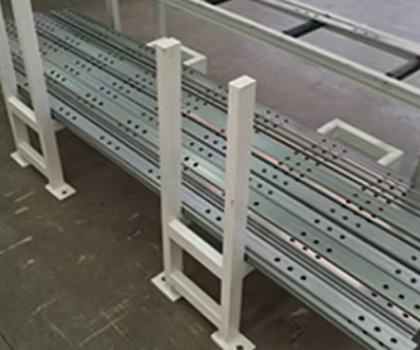
Quality inspection should occur during production, not only before shipment.
A modern PV bracket factory should provide dedicated space for:
- Incoming material inspection
- First-article inspection
- In-process dimensional checks
- Connector-fit testing
- Surface inspection
- Final batch release
First-Article Inspection
After a setup or changeover, check:
- Profile dimensions
- Bend angles
- Hole pattern
- Cut length
- Straightness
- Twist
- Burrs
- Coating condition
- Assembly fit
Production should begin only after the first article is accepted.
In-Process Inspection
Repeat inspection after:
- Coil changes
- Tool changes
- Roller adjustments
- Punch sharpening
- Cutter replacement
- Alarms
- Production interruptions
Tool wear and material variation can change the product after the first article has passed.
Measurement Equipment
Depending on the product, inspection may use:
- Calipers
- Micrometers
- Height gauges
- Angle gauges
- Tape measures
- Straightedges
- Surface plates
- Profile fixtures
- Coordinate measuring equipment
- Optical measurement
All instruments should have suitable range, resolution and calibration status.
11. Packaging and Finished-Product Storage
Packaging should protect products while preserving identification.
A finished bundle may include:
- Product code
- Drawing revision
- Quantity
- Batch number
- Material batch
- Production date
- Inspection status
- Destination
- Handling instructions
Dry and Ventilated Storage
Galvanized profiles should be protected from trapped moisture. Closely stacked wet components can develop staining.
Storage should include:
- Dry flooring
- Drainage
- Ventilation
- Protection from rain
- Separation from chemicals
- Controlled bundle support
- Clear shipment lanes
Separate Accepted and Unapproved Products
Finished products awaiting inspection should not be stored with released batches.
Use clearly defined statuses such as:
- Awaiting inspection
- Accepted
- Rework
- Rejected
- Ready for shipment
12. Digital Production Control
Modern manufacturing uses production data to support decisions rather than relying only on operator memory.
NIST’s work on smart manufacturing addresses measurement, control and information technologies that support more connected manufacturing systems.
A PV bracket factory may record:
- Product recipe
- Drawing revision
- Coil batch
- Production quantity
- Qualified quantity
- Rejected quantity
- Downtime
- Alarm history
- Tooling status
- Energy use
- Maintenance records
Product Recipes
Recipes can store:
- Hole patterns
- Product length
- Batch quantity
- Feeder positions
- Cutting commands
- Adjustable-axis positions
Recipe access should be controlled, and critical changes should be recorded.
Production Traceability
Traceability connects a finished bundle with:
- Material
- Machine
- Tooling
- Operator
- Inspection
- Production time
This makes defect investigation and repeat production more reliable.
13. Maintenance Workshop and Spare Parts
A factory cannot maintain stable output without access to tools and critical spare parts.
The maintenance area may store:
- Punches and dies
- Cutting blades
- Bearings
- Sensors
- Encoders
- Hydraulic seals
- Filters
- Lubricants
- Electrical components
- Roller drawings
- Calibration tools
Tooling Storage
Rollers and punching tools should be:
- Clearly identified
- Protected from corrosion
- Stored in defined locations
- Connected with product drawings
- Recorded after maintenance
- Inspected before installation
Maintenance Access Around the Line
The factory layout should leave enough space to:
- Remove rollers
- Change punching dies
- service hydraulic equipment
- Open electrical cabinets
- Replace motors
- Lift major components
- Clean scrap chutes
A compact layout that prevents safe maintenance may create longer downtime later.
14. Factory Utilities and Infrastructure
A complete PV bracket factory may require:
- Electrical power
- Compressed air
- Hydraulic systems
- Cooling
- Network connection
- Lighting
- Ventilation
- Cranes
- Forklifts
- Fire protection
- Safety fencing
Electrical Planning
Confirm:
- Voltage
- Frequency
- Installed load
- Peak demand
- Distribution panels
- Cable routes
- Grounding
- Backup requirements
Compressed Air
Pneumatic systems may operate:
- Clamps
- Marking units
- Scrap removal
- Product transfer
- Safety devices
Pressure, flow and air quality should match the machine specification.
Network and Data
Remote diagnostics, production reporting and factory-system integration require controlled network access.
The factory should define:
- Connection method
- User permissions
- Cybersecurity responsibility
- Data ownership
- Backup
- Remote-access approval
15. Material and Personnel Flow
Machines are only part of the layout. Operators, maintenance staff, forklifts and cranes also move through the facility.
A good layout separates:
- Pedestrian walkways
- Forklift routes
- Coil transport
- Finished-product transport
- Maintenance access
- Emergency exits
Avoid Crossing Routes
Raw material should enter near the beginning of production. Finished products should leave from the opposite or clearly separated area where practical.
Repeated crossing increases:
- Handling time
- Collision risk
- Product damage
- Production interruption
Provide Inspection Space Near Production
Quality staff should not need to carry long profiles through several production areas for routine measurement.
An inspection point near the line allows faster first-article approval.
Basic, Semi-Automatic and Automated Factory Models
| Factory model | Main features | Suitable conditions |
|---|---|---|
| Basic | Manual coil handling and stacking | Moderate output and stable products |
| Semi-automatic | Automated feeding, punching, forming and cutting | Growing volume with controlled investment |
| Automated | Connected loading, forming, cutting, stacking and data collection | High output and multi-shift operation |
| Flexible multi-line | Dedicated and adjustable cells | Broad product range and varied batches |
A fully automated factory is not automatically the most efficient. Automation should address confirmed bottlenecks and match the product mix.
Measuring PV Bracket Factory Performance
Useful performance indicators include:
| Metric | Purpose |
|---|---|
| Qualified pieces per shift | Measures actual output |
| Tons or meters per day | Supports material planning |
| Changeover time | Measures production flexibility |
| Coil-change time | Measures entry-section efficiency |
| Setup scrap | Shows material loss |
| Rejection rate | Measures quality loss |
| Downtime by reason | Identifies bottlenecks |
| Tool life | Supports maintenance planning |
| Energy per qualified product | Connects utilities with output |
| On-time batch completion | Measures production reliability |
The global photovoltaic market continues to develop across multiple applications. The International Energy Agency Photovoltaic Power Systems Programme publishes reports on photovoltaic deployment and industry trends. Factory planning, however, should translate market opportunity into specific profiles, batch sizes and capacity requirements.
Common PV Bracket Factory Layout Mistakes
Selecting Equipment Before Finalizing Products
Machine design should follow profile drawings, materials and hole patterns.
Comparing Only Forming Speed
Punching, cutting and stacking may determine total output.
Placing Machines Without Material Routes
A machine can fit physically while creating inefficient forklift and operator movement.
Ignoring Tooling Storage
Uncontrolled tooling increases changeover time and damage.
Providing Insufficient Inspection Space
Slow first-article approval reduces available production time.
Mixing Accepted and Unapproved Products
Poor status control creates shipment and traceability risks.
Leaving No Expansion Area
Future punching, stacking or secondary-processing equipment may become difficult to add.
Underestimating Maintenance Clearance
Technicians need safe access to rollers, dies, cutters, drives and electrical systems.
Information Needed for a Factory Proposal
Before requesting a complete factory or production-line proposal, prepare:
Product Information
- Profile drawings
- Connector drawings
- Length range
- Hole patterns
- Tolerances
- Product samples
Material Information
- Material grade
- Strength
- Thickness
- Coil dimensions
- Coil weight
- Coating
- Surface requirements
Production Information
- Annual volume
- Pieces per shift
- Number of shifts
- Batch sizes
- Product mix
- Changeover frequency
- Expected expansion
Factory Information
- Workshop drawing
- Column positions
- Door dimensions
- Floor capacity
- Crane capacity
- Voltage and frequency
- Compressed-air supply
- Raw-material entrance
- Finished-product exit
Conclusion
A modern PV bracket factory is a coordinated manufacturing system rather than a collection of separate machines.
Raw-material receiving, coil storage, leveling, punching, roll forming, cutting, inspection, stacking and packaging should follow a clear workflow. Digital recipes, traceability, downtime records and energy monitoring can strengthen production control when they are connected with practical factory decisions.
The layout should be based on actual bracket drawings, materials, hole patterns, tolerances, batch sizes and output targets. It should also reserve safe access for operators, maintenance, cranes, forklifts and future expansion.
Jinbolida provides photovoltaic forming, punching, cutting and automated material-handling solutions for factories producing rails, channels, posts and connectors. Manufacturers can submit product drawings, material information, capacity targets and workshop layouts through the Jinbolida contact page for a customized PV bracket factory evaluation.
FAQ
What machines are required in a PV bracket factory?
A typical factory may need coil handling, decoiling, leveling, servo feeding, punching, roll forming, cutting, receiving and stacking equipment. Short connectors may require separate punching and forming systems. The final configuration depends on profile drawings, materials, hole patterns, batch sizes and automation requirements.
Should punching be integrated with the roll forming line?
Inline punching reduces material transfers and supports coordinated feeding, forming and cutting. It is suitable for stable repeated patterns. Separate punching offers independent scheduling and can serve varied batches or multiple lines. The correct arrangement depends on cycle time, product mix, floor space and required flexibility.
How much factory space is needed for PV bracket production?
The required area depends on coil storage, machine length, product length, punching, stacking, inspection, maintenance clearances and material routes. A complete automated line needs more than its listed machine footprint. Request a general arrangement drawing that includes cranes, forklifts, operators and finished-product storage.
What is the main bottleneck in a PV bracket factory?
The bottleneck may be punching, cutting, coil replacement, profile changeover, inspection or stacking. The roll former is not always the constraint. Measure every repeated operation using an actual product and track both major downtime and frequent minor stops before deciding where to add speed or automation.
How should PV bracket production be traced?
Assign each coil and finished batch a unique identification. Connect the material certificate, product recipe, drawing revision, machine, tooling, operator, production time and inspection records. This allows the factory to investigate deviations, isolate affected products and reproduce approved settings for later orders.
 English
  Arabic
  Russian
  Spanish
  French