
Roll Forming Machine Commissioning: What to Check
Table of Contents
Introduction

Installing a roll forming line does not mean the equipment is ready for stable production. Before continuous manufacturing begins, the machine needs to be checked, aligned, tested, adjusted, and verified under actual operating conditions. This process is known as roll forming machine commissioning.
Commissioning connects machine installation with real production. It confirms that the machine is mechanically installed correctly, electrical and hydraulic systems operate as intended, tooling is aligned, material travels through the line properly, safety functions respond correctly, and finished profiles meet the required drawing.
A good commissioning process should not focus only on whether the machine can run. The real objective is to determine whether the complete production line can repeatedly produce acceptable parts under the agreed material, tooling, speed, punching, cutting, and automation conditions.
For manufacturers preparing a new line, commissioning should therefore follow a structured sequence from installation verification to continuous production testing.
What Is Roll Forming Machine Commissioning?
Roll forming machine commissioning is the systematic process used to verify that a newly installed or significantly modified roll forming line is ready for production.
It usually begins after mechanical installation is complete and continues until the machine has successfully produced stable finished profiles.
Depending on the equipment configuration, commissioning may include:
- machine leveling,
- foundation and anchor inspection,
- stand alignment,
- shaft inspection,
- tooling installation,
- lubrication,
- gearbox checks,
- hydraulic testing,
- pneumatic testing,
- electrical verification,
- PLC and HMI checks,
- sensor calibration,
- servo feeder testing,
- punching tests,
- roll forming trials,
- cutting tests,
- safety-system verification,
- first-piece inspection,
- and continuous production validation.
A roll forming line containing only forming and cutting equipment will require a simpler commissioning process than a highly automated production system integrating feeding, punching, forming, cutting, transfer, stacking, and robotic handling.
The commissioning plan should therefore reflect the actual machine configuration.
Why Commissioning Is Critical Before Production
Many roll forming problems that appear during production actually originate during installation or initial setup.
A machine stand may be slightly out of level.
A tooling spacer may be installed in the wrong position.
A guide may not follow the intended centerline.
A sensor may respond correctly during manual testing but fail at normal line speed.
A cut-off unit may operate but produce inconsistent finished lengths.
These issues can remain hidden when the machine is tested only at low speed or without material.
Once continuous production begins, small errors can combine and become more visible.
Typical results include:
- profile twist,
- inconsistent dimensions,
- poor hole positioning,
- strip tracking problems,
- surface marks,
- cutting deformation,
- unstable automation,
- or frequent machine alarms.
Commissioning provides an opportunity to identify these conditions before regular production begins.
Commissioning Should Begin Before the Machine Is Powered On
The first commissioning checks should be mechanical rather than operational.
Before powering the line, confirm that the machine has been installed according to the intended layout.
Important items include:
- machine foundation,
- anchor points,
- floor condition,
- line orientation,
- machine-to-machine spacing,
- electrical access,
- operator access,
- maintenance clearance,
- coil-loading space,
- and finished-product handling area.
For a complete production line, the relationship between individual machines is important.
The decoiler, leveler, feeder, punch, forming machine, cutting section, and receiving system should follow the intended material centerline.
If equipment is installed at different lateral positions, material may need to change direction while moving through the line.
That can create tracking problems that later appear to be tooling or forming defects.
Check Machine Leveling
A roll forming machine should operate from a stable and correctly leveled foundation.
Leveling affects the relationship between forming stands and the material path.
If one part of the machine frame sits higher or lower than another, the tooling centerline may not remain consistent through the full length of the machine.
The commissioning team should verify machine level using appropriate measuring equipment at designated reference locations.
The correct procedure depends on the machine design.
It is important to avoid checking only one point on the frame. Long production lines should be evaluated across multiple reference positions.
Once leveling is completed, anchor bolts and support points should be secured according to the installation procedure.
Machine level should also be rechecked after final tightening because the fixing process itself can slightly alter frame position.
Verify the Production Line Centerline
Centerline alignment is one of the most important commissioning checks.
Material should move from the beginning of the line to the end without being forced sideways by guides or tooling.
The centerline may pass through:
decoiler → leveler → feeder → punching → forming → cutting → receiving
If each section references a different lateral position, operators may compensate using aggressive guide adjustments.
This can cause strip friction, camber, twist, or uneven forming.
Commissioning should therefore establish one clear production centerline and verify the position of each major piece of equipment relative to it.
This is especially important when several machines were installed independently at different times.
Inspect Roll Forming Stands
Before tooling trials begin, inspect the forming stands mechanically.
Check whether stands are securely mounted and positioned correctly.
The relationship between upper and lower shafts should be reviewed according to the machine design.
Potential issues include:
- loose stand fasteners,
- shaft movement,
- damaged bearings,
- incorrect spacers,
- contaminated mounting surfaces,
- or damage during transport.
The commissioning team should not assume that factory alignment automatically remains unchanged after transportation and installation.
Large machinery can experience movement during handling.
Verifying the forming section at the installation site creates a reliable starting point before production adjustments begin.
Confirm Tooling Installation
Roll tooling should be installed according to the designated station sequence.
Each roll normally belongs to a specific forming position.
Installing one roller or spacer incorrectly can change the intended flower pattern and create downstream problems that are difficult to diagnose.
During commissioning, verify:
- roller identification,
- left/right orientation,
- upper/lower roll position,
- spacer order,
- shaft fixing,
- side-roll position,
- tooling cleanliness,
- and visible damage.
Tooling surfaces should be clean before material is introduced.
Foreign particles between the roller and strip can immediately create repeated surface marks on the first test material.
The tooling setup should correspond with the approved product drawing and forming design rather than relying on visual approximation.
Check Roll Gaps Before Trial Forming
Roll gap influences how the material contacts the tooling.
If the forming stands are excessively tight, material can be overworked, marked, or distorted.
If the gaps are too large, the rollers may not control the profile correctly.
Initial roll gaps should therefore follow the tooling and machine setup procedure.
Operators should avoid tightening all stands simply because the strip appears loose.
Roll forming depends on progressive deformation.
Each stand should perform its intended portion of the forming process rather than squeezing the profile unnecessarily.
Baseline gap settings should be documented during successful commissioning so they can be referenced during future changeovers.
Confirm Lubrication Before Running the Machine
Mechanical systems should not begin commissioning without the required lubrication.
Check:
- gearbox oil,
- bearing lubrication,
- chain lubrication,
- guide lubrication,
- hydraulic oil,
- and other specified lubrication points.
Fluid levels should correspond with machine requirements.
The commissioning team should also inspect for leaks before and after initial operation.
Running a gearbox or bearing assembly without adequate lubrication can cause damage before the machine reaches normal production.
Initial operation is also a useful time to confirm that automatic lubrication systems, where fitted, are delivering lubricant correctly.
Inspect the Drive System
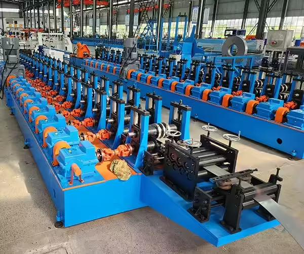
The drive system transfers power to the forming stands.
Before loaded testing, inspect:
- motors,
- gearboxes,
- couplings,
- chains,
- sprockets,
- shafts,
- guards,
- and fastening points.
The machine should initially be operated at low speed without material when the commissioning procedure permits.
Listen for unusual:
- knocking,
- grinding,
- chain noise,
- vibration,
- or gearbox sound.
Abnormal noise should be investigated before loading material.
Increasing speed when an unexplained mechanical sound is present can make diagnosis more difficult and may increase damage.
Electrical System Verification
Electrical commissioning should confirm that power distribution, control circuits, drives, and safety systems operate according to the intended design.
Typical checks include:
- supply voltage,
- grounding,
- motor rotation direction,
- electrical cabinet condition,
- drive communication,
- PLC operation,
- HMI operation,
- sensors,
- switches,
- encoders,
- alarms,
- and emergency-stop circuits.
Motor rotation direction should be confirmed before material enters the line.
A motor turning in the wrong direction can create immediate mechanical problems.
Electrical cabinets should also be checked for loose connections that may have developed during transportation.
Commissioning is the appropriate time to resolve communication faults and sensor errors before the machine enters normal production.
Verify PLC and HMI Functions
Modern roll forming lines commonly use PLC control and an HMI for production settings.
The commissioning team should test the available operating modes.
These may include:
- manual mode,
- setup mode,
- automatic mode,
- jogging,
- recipe selection,
- production quantity,
- length setting,
- punching pattern,
- alarm reset,
- and system diagnostics.
Each function should be verified under safe commissioning conditions.
Displayed values should also correspond with actual machine behavior.
For example, entering a cut length on the HMI does not prove the finished profile will have exactly that length.
The value still needs to be confirmed through material trials.
The control system provides commands; commissioning verifies the physical result.
Test Every Sensor
Sensors coordinate many automated operations.
A faulty or incorrectly positioned sensor can create intermittent problems that appear only during continuous production.
Test sensors associated with:
- material presence,
- feed position,
- punching position,
- cut-off position,
- cylinder position,
- safety doors,
- limit switches,
- product detection,
- and receiving systems.
Where possible, confirm both the signal and the physical triggering point.
A sensor may produce an electrical signal while still being mounted too far from the correct mechanical position.
Sensor brackets should also be secure enough that vibration does not change the trigger location during operation.
Hydraulic System Commissioning
Roll forming lines may use hydraulic power for:
- decoiler expansion,
- punching,
- cutting,
- clamping,
- adjustment,
- or material handling.
Before production trials, confirm:
- oil level,
- pump operation,
- operating pressure,
- hose condition,
- fittings,
- valves,
- cylinders,
- filters,
- and leaks.
The hydraulic system should operate repeatedly without unstable pressure or abnormal temperature rise.
Punching and cutting functions should be tested first without production material when appropriate.
The objective is to confirm mechanical movement and control synchronization before adding the additional complexity of strip feeding.
Pneumatic System Checks
Where pneumatic devices are used, check:
- air pressure,
- regulators,
- filters,
- valves,
- cylinders,
- hoses,
- fittings,
- and leaks.
Pneumatic actuators should move smoothly and return consistently.
Slow movement should not automatically be corrected by increasing pressure.
The cause may be a restricted line, leaking connection, damaged cylinder, or valve problem.
Commissioning should establish stable operating conditions rather than temporary compensation.
Safety Systems Must Be Tested Before Production
Safety validation is a core commissioning requirement.
Emergency-stop buttons should be tested individually.
Safety doors, interlocks, guarding, light curtains, and other devices should be checked according to the machine configuration.
The line should respond correctly when a safety circuit is activated.
Resetting should also require the intended operator action rather than allowing uncontrolled automatic restart.
The U.S. Occupational Safety and Health Administration provides machine guarding requirements addressing hazards such as points of operation, rotating parts, nip points, and flying material.
Commissioning procedures should follow applicable local safety requirements and the machine manufacturer’s instructions.
Perform No-Load Testing First
Before introducing steel, the production line should normally be tested without load where the machine procedure allows.
No-load testing confirms whether mechanical and control systems operate together.
Typical checks include:
- motor direction,
- speed adjustment,
- forming stand rotation,
- feeder motion,
- punch movement,
- cutting cycles,
- hydraulic functions,
- sensors,
- alarms,
- and emergency stops.
Run the equipment initially at lower speed.
Observe whether chains, shafts, couplings, and other moving components operate smoothly.
After a suitable trial, stop the machine and inspect for:
- loose fasteners,
- abnormal temperature,
- leakage,
- unusual wear,
- or components that moved from their original positions.
Only after the machine behaves normally without material should loaded commissioning proceed.
Prepare the Correct Trial Material
Trial material should reflect the actual production specification whenever practical.
Using material with a significantly different:
- thickness,
- width,
- strength,
- coating,
- or mechanical behavior
can produce misleading commissioning results.
The tooling was designed around a particular material range.
If the trial coil differs substantially from the intended production material, adjustments made during commissioning may not transfer successfully to normal operation.
Before feeding the strip, verify:
- material grade,
- thickness,
- strip width,
- surface condition,
- coil condition,
- and edge quality.
Trial material should also be sufficient for more than one short sample. Stable commissioning requires observing the line over enough material to identify repeatability.
Test Decoiling and Material Entry
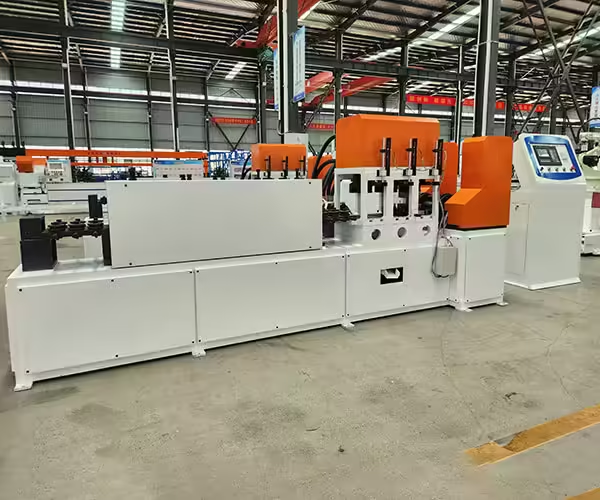
The first loaded test begins at the entry section.
Confirm that the coil is centered correctly on the decoiler.
Material should unwind without uncontrolled lateral movement.
Check braking or tension behavior according to the machine design.
The strip should then enter the leveler or feeder without excessive forcing.
Guides should reference the strip while allowing smooth material movement.
An incorrectly centered coil can create strip tracking problems that become increasingly visible farther downstream.
Commissioning should therefore correct material position at the beginning of the line instead of using later guides to compensate.
Verify Leveling Performance
If the line includes a leveler, inspect the material after leveling.
The objective is to reduce coil set and create a stable strip condition for downstream punching and forming.
Improper leveling can introduce new curvature rather than removing existing coil memory.
Check whether the strip leaves the leveler:
- reasonably flat,
- centered,
- without excessive marking,
- and without unintended wave.
Leveling settings should be documented for representative materials.
Different thicknesses and strengths may require different settings.
Servo Feeder Commissioning
When a servo feeder controls punching or cutting position, actual material movement must be verified.
Start with a simple programmed feed length.
Run several repeated feeds and measure the physical strip movement or finished feature spacing.
Check for:
- slip,
- inconsistent roller pressure,
- excessive acceleration,
- encoder problems,
- upstream tension,
- or incorrect calibration.
Programmed feed distance and actual feed distance should correspond within the required process tolerance.
For multiple-product lines, representative production recipes should also be tested.
Servo-feeder performance should be evaluated under the actual material condition rather than only with the rollers turning empty.
Commissioning the Punching Section
If the line includes punching, begin with low-speed or single-cycle tests.
Verify:
- punch and die alignment,
- hole shape,
- hole dimensions,
- burr condition,
- feed position,
- tool clearance,
- hydraulic or mechanical operation,
- and synchronization.
The first question is whether the hole is created correctly.
The second is whether it appears in the correct location.
The third is whether the position remains consistent across repeated cycles.
When punching occurs before roll forming, final hole position should also be checked after the profile has been fully formed.
Subsequent bending can change how a punched feature relates to the finished cross-section.
Thread Material Through the Roll Forming Section Carefully
Initial threading should be performed according to the machine’s operating procedure.
The strip should enter each forming stand in the intended position.
Observe how the profile changes from pass to pass.
This is one of the most useful stages of commissioning because it shows whether the strip follows the intended flower pattern.
Do not inspect only the final stand.
Check intermediate profile development.
If a flange begins moving incorrectly at stand four, attempting to correct the problem only at stand ten can create additional stress.
The goal is to identify the earliest point where the actual profile begins to differ from the intended forming progression.
JBLDIE’s roll forming machine guide provides additional background on how a profile develops through multiple forming stations.
Check Strip Tracking Through Every Stand
The strip should remain aligned with the machine centerline throughout the forming section.
Warning signs include:
- increasing contact with one guide,
- lateral movement,
- unequal flange development,
- edge rubbing,
- or profile rotation.
If tracking begins to drift, investigate where the movement starts.
Possible causes include:
- incorrect entry-guide position,
- stand misalignment,
- tooling installation error,
- unequal roll gaps,
- incoming strip camber,
- or asymmetric forming forces.
Do not use aggressive side-guide pressure as the first solution.
Guides should help establish and maintain position, not force incorrectly formed material back toward the centerline.
Inspect the Profile After Each Major Forming Stage
During commissioning, intermediate inspection provides valuable information.
Measure or visually compare the profile at selected stands.
Depending on the geometry, check:
- bend development,
- flange position,
- web condition,
- edge wave,
- twist,
- surface contact,
- and symmetry.
For complex profiles, temporary samples can be cut during commissioning to examine the geometry after specific passes.
This allows tooling problems to be identified earlier.
Once the complete line is running at normal speed, this type of detailed stand-by-stand analysis becomes more difficult.
Commissioning is therefore the best time to establish how a correctly formed profile should look at intermediate stages.
Set the Straightening Section Carefully
A straightener should make controlled final corrections to the profile.
It should not be used to hide major upstream forming errors.
During commissioning, first evaluate the profile leaving the final forming stand.
If significant bow, twist, or camber already exists, investigate the forming process before applying aggressive straightener adjustments.
Once upstream forming is stable, the straightener can be adjusted to improve final longitudinal geometry.
Record successful straightener settings for future reference.
Different material thicknesses or profiles may require different correction values.
Commission the Cutting System
The cutting section should be tested after the profile shape is stable.
Verify:
- cutting position,
- cut completeness,
- end deformation,
- burr condition,
- finished length,
- sensor timing,
- and cycle synchronization.
For profile cut-off dies, confirm that the tooling supports the cross-section correctly during cutting.
A cut-off system that distorts the profile end can make a stable roll forming process appear inaccurate.
Finished lengths should be measured across multiple consecutive parts.
One correct sample does not confirm repeatability.
Check the Finished Profile Against the Drawing
Once the complete process is operating, perform a detailed first-piece inspection.
Depending on the product, this may include:
- overall width,
- overall height,
- flange dimensions,
- web dimensions,
- bend angles,
- hole positions,
- slot positions,
- straightness,
- camber,
- twist,
- cut length,
- surface condition,
- and end geometry.
Measurements should use clearly defined datums.
Inspection should not rely only on visual comparison.
The first acceptable profile establishes a commissioning baseline.
Once approved, important machine and control settings should be documented.
Roll Forming Machine Commissioning Checklist
| Commissioning Area | What to Verify |
|---|---|
| Machine installation | Foundation, anchors, spacing |
| Machine leveling | Frame and stand reference level |
| Centerline | Alignment across complete production line |
| Forming stands | Position, fastening, shaft condition |
| Tooling | Correct sequence and orientation |
| Roll gaps | Baseline forming settings |
| Lubrication | Oil, grease and delivery |
| Drive system | Motor, gearbox, chains, couplings |
| Electrical system | Power, grounding, drives, controls |
| PLC/HMI | Operating modes and recipes |
| Sensors | Position and signal reliability |
| Hydraulics | Pressure, leaks, valves, cylinders |
| Pneumatics | Pressure, leaks, actuator movement |
| Safety | Guards, interlocks, emergency stops |
| Decoiling | Coil center and strip delivery |
| Leveling | Strip flatness |
| Servo feeding | Actual feed accuracy |
| Punching | Hole quality and position |
| Roll forming | Profile progression and tracking |
| Straightening | Bow, camber and twist correction |
| Cutting | Length and end condition |
| Final inspection | Drawing compliance |
| Continuous test | Repeatability over production run |
Do Not Stop at One Good Sample
Producing one acceptable profile is not the end of commissioning.
A machine can produce one good part after manual adjustments while still being unstable during continuous operation.
After first-piece approval, the line should run for a meaningful continuous period under representative conditions.
The objective is to determine whether dimensions remain stable as:
- machine temperature changes,
- material moves continuously,
- punching cycles repeat,
- cutting cycles accumulate,
- and operating speed increases.
Several consecutive finished profiles should be inspected.
If dimensions drift gradually, commissioning should identify the cause before the machine is released for production.
Increase Speed Gradually
A line that produces acceptable profiles at low speed may behave differently at normal production speed.
Higher speed changes:
- material dynamics,
- acceleration,
- vibration,
- servo timing,
- punching cycle requirements,
- cutting synchronization,
- and handling.
Commissioning should therefore increase speed progressively.
At each stage, verify:
- strip tracking,
- profile dimensions,
- sensor stability,
- punching accuracy,
- cutting performance,
- abnormal vibration,
- and finished-part quality.
The goal is to establish stable production at the required operating condition rather than reaching maximum machine speed as quickly as possible.
Test Representative Product Changeovers
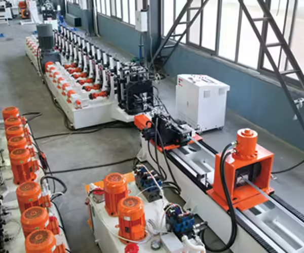
If the line is designed for multiple profiles or sizes, commissioning should include representative changeovers.
A successful line should not only produce the first installed profile.
It should also demonstrate that approved setup procedures can reproduce other required specifications.
Depending on the machine, changeover may involve:
- tooling replacement,
- spacer changes,
- guide adjustment,
- roll-gap adjustment,
- punching-tool changes,
- straightener settings,
- cut-off tooling,
- servo programs,
- and PLC recipes.
Record the process from the last acceptable part of one product to the first acceptable part of the next.
This provides practical information about production flexibility.
Test Automation Under Real Production Conditions
An automated production line should be commissioned as a complete system.
Individual machines may operate correctly in manual mode while failing to coordinate reliably in automatic mode.
Test interactions between:
- feeder and punch,
- punch and roll former,
- roll former and cut-off,
- cut-off and conveyor,
- transfer equipment and stacker,
- alarms and line stop,
- and central PLC communication.
Simulate realistic abnormal conditions where appropriate.
For example, what happens if a product does not reach a downstream sensor?
Does the line stop safely?
Does the HMI identify the correct fault?
Can production restart without losing the process sequence?
These situations are easier to resolve during commissioning than after regular production begins.
Record Approved Settings
One of the most valuable outputs from commissioning is a set of baseline parameters.
These may include:
- tooling arrangement,
- roll gaps,
- guide positions,
- feeder settings,
- punching recipes,
- straightener settings,
- cut lengths,
- speed parameters,
- and product-specific control values.
Successful settings should not remain only in one engineer’s memory.
Documented baselines help operators restore the machine after:
- changeover,
- maintenance,
- tooling removal,
- sensor replacement,
- or process troubleshooting.
They also make future production more repeatable.
Train Operators During Commissioning
Commissioning is also an important training period.
Operators should understand not only which buttons to press but how the complete process works.
Training should include:
- startup,
- shutdown,
- product selection,
- coil loading,
- threading,
- guide adjustment,
- normal production,
- quality checks,
- alarm response,
- safe access,
- changeover,
- and basic troubleshooting.
Maintenance personnel should understand lubrication, mechanical inspection, electrical systems, hydraulic systems, and scheduled service requirements.
A production line is more likely to remain stable when operators understand why specific settings matter.
Common Commissioning Problems
Profile Twist
Check entry alignment, tooling installation, stand position, roll gaps, and asymmetric forming conditions.
Unequal Flange Dimensions
Confirm strip width, centerline, guide position, tooling sequence, and bend locations.
Hole Position Errors
Check servo-feed accuracy, punching synchronization, program values, and final position after forming.
Surface Marks
Inspect roll surfaces, guides, debris, material condition, and excessive tooling pressure.
Cut Length Variation
Check measuring devices, servo feed, encoder signals, cut-off timing, and strip slip.
Frequent Sensor Alarms
Check physical sensor position, mounting stability, wiring, trigger distance, and PLC logic.
Excessive Vibration
Inspect stands, bearings, shafts, drive components, anchors, and tooling balance.
Troubleshooting should identify where the problem first appears rather than changing multiple unrelated settings at once.
Factory Acceptance Test vs Site Commissioning
Factory Acceptance Testing (FAT) and site commissioning serve different purposes.
FAT is normally performed before shipment to verify that the machine has been built and can demonstrate agreed functions.
Site commissioning occurs after installation at the final production location.
During site commissioning, several new variables appear:
- local foundation,
- electrical supply,
- machine positioning,
- installation accuracy,
- actual material,
- final production layout,
- and operator interaction.
A machine that performed well during FAT should therefore still undergo structured site commissioning.
Shipment and installation can change conditions that need to be verified again.
Site Acceptance Should Focus on Finished Output
A useful site acceptance process should evaluate the finished component rather than only machine movement.
The line should be tested using agreed material and representative production requirements.
Acceptance can include:
- machine function,
- production sequence,
- profile dimensions,
- punching accuracy,
- cut length,
- surface quality,
- repeatability,
- operating speed,
- and changeover where required.
For manufacturers evaluating roll forming equipment, finished-profile requirements should therefore be discussed before commissioning so both sides understand what will be verified.
Handover Documentation
Before commissioning is completed, the production team should receive the relevant machine documentation.
Depending on the project, this can include:
- operating manual,
- electrical drawings,
- hydraulic diagrams,
- pneumatic diagrams,
- tooling information,
- maintenance schedule,
- lubrication requirements,
- spare-parts information,
- production recipes,
- commissioning records,
- and training materials.
Documentation supports future troubleshooting and maintenance.
Without proper records, a factory may become unnecessarily dependent on individual operator memory.
Conclusion
Roll forming machine commissioning is the process that converts newly installed equipment into a verified production system.
A complete commissioning program should begin with foundation, leveling, centerline, stands, tooling, lubrication, drives, electrical systems, hydraulics, pneumatics, controls, and safety. It should then progress through no-load testing, material threading, feeding, punching, roll forming, straightening, cutting, first-piece inspection, continuous operation, speed increase, and representative changeovers.
The most important commissioning result is not simply that the machine moves.
It is that the complete line can repeatedly manufacture finished profiles that meet the agreed drawing under realistic production conditions.
Documenting successful settings, verifying automation, training operators, and establishing inspection baselines during commissioning also creates a stronger foundation for future maintenance and process control.
For manufacturers preparing a new roll forming line, systematic commissioning helps identify installation and setup problems before they become recurring production problems.
FAQ
What is roll forming machine commissioning?
Roll forming machine commissioning is the process of checking, testing, adjusting, and verifying a newly installed roll forming line before normal production. It includes mechanical, electrical, control, tooling, safety, and finished-product checks.
What should be checked before running a roll forming machine?
Important checks include machine leveling, centerline alignment, stand and tooling installation, lubrication, drive systems, electrical controls, hydraulics, sensors, guards, emergency stops, and material-handling equipment.
Why should a roll forming machine be tested at low speed first?
Low-speed testing makes it easier to observe strip tracking, forming progression, sensors, punching, cutting, vibration, and other process conditions before dynamic effects increase at normal operating speed.
Is one acceptable profile enough to complete commissioning?
No. Several consecutive profiles should be produced and inspected to verify repeatability. Continuous testing also helps identify dimensional drift, sensor instability, cutting variation, and other problems that may not appear in a single sample.
What information should be recorded during commissioning?
Useful records include tooling arrangement, roll gaps, guide positions, feeder settings, punching programs, straightener settings, cutting parameters, speed values, finished-profile measurements, and approved production recipes.
Need to Prepare a Roll Forming Line for Production?
Successful commissioning begins with the actual profile drawing, material, tooling, punching requirements, cutting method, automation sequence, and finished-product tolerances. If you are evaluating a new production line, contact JBLDIE to discuss your profile and manufacturing requirements.
 English
  Arabic
  Russian
  Spanish
  French