
Roll Forming Machine Guide: From Coil to Qualified Profile
Table of Contents
A roll forming machine converts continuous metal strip into profiles with a consistent cross-section. Instead of completing a full bend in one operation, the machine moves the strip through a sequence of roller stations. Each station performs a controlled part of the total deformation until the required profile is produced.
However, producing a qualified profile requires more than passing material through rollers. Coil condition, leveling, entry alignment, tooling design, shaft accuracy, punching, cutting and finished-product handling all affect the final result.
This guide explains:
- How the roll forming process works
- Which components make up a complete production line
- How material properties affect forming
- Why roller design and alignment influence accuracy
- How punching and cutting can be integrated
- What causes twist, bow, waves and dimensional variation
- How to evaluate real production capacity
- Which quality checks should be completed
- How to select a machine for a specific profile
A roll forming machine is most suitable for producing long metal components with a constant cross-section and repeated dimensions. Typical applications include C-, U-, Z-, W- and L-shaped profiles, solar mounting brackets, roofing panels, structural channels, highway barriers, steel formwork components and industrial support sections.
What Is a Roll Forming Machine?
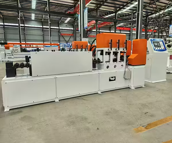
A roll forming machine is an industrial metal-forming system that gradually bends a continuous strip through multiple pairs of contoured rollers. Each roller station makes a small dimensional change, allowing the strip to reach its final shape without completing all bends at once.
The general principle of roll forming makes the process suitable for repeated production of long profiles. Once the tooling and machine settings have been correctly established, the same section can be continuously manufactured from coil material.
Unlike a press brake, which normally forms individual blanks, a roll forming line can combine several operations in one connected production process.
Depending on the finished product, a complete line may perform:
- Decoiling
- Leveling
- Servo feeding
- Punching
- Notching
- Marking
- Progressive forming
- Welding
- Measuring
- Cutting
- Receiving
- Stacking
- Bundling
Jinbolida supplies different forming solutions for photovoltaic brackets, construction profiles, W-, L- and Z-shaped steel, traffic barriers and customized industrial components. These applications can be reviewed through the company’s roll forming machine product categories.
How a Roll Forming Machine Works
A flat metal strip does not immediately enter the final roller shape. The deformation is divided into a carefully designed series of forming stages.
Coil Loading and Decoiling
The process begins with loading the metal coil onto a decoiler. The decoiler supports the coil and releases material into the production line at a controlled rate.
Its size and structure should match:
- Maximum coil weight
- Coil inner diameter
- Coil outer diameter
- Strip width
- Line speed
- Required expansion method
A manual decoiler may be sufficient for light coils and low production volumes. Heavy or continuously operated lines normally require powered or hydraulic expansion, controlled rotation and a suitable coil-loading method.
An incorrectly centered coil can cause the strip to move sideways before it reaches the forming machine. The problem may later appear as uneven flanges, inaccurate punching or excessive pressure against the entry guides.
Leveling the Strip
Coiled material naturally retains curvature. A leveling unit reduces this coil set and prepares a more stable strip for feeding, punching and forming.
Poor leveling can lead to:
- Unstable feeding
- Inaccurate hole locations
- Uneven roller contact
- Profile bow
- Dimensional variation
- Irregular cutting length
The leveler should be adjusted for the material thickness and strength. Excessive pressure can mark the surface or introduce new distortion, while insufficient pressure may leave too much coil curvature.
Guiding and Feeding
The entry guide centers the strip before it enters the forming stations. Servo feeders may also position the material for punching or cutting.
Stable feeding depends on:
- Correct strip width
- Consistent material thickness
- Clean guide surfaces
- Accurate guide alignment
- Sufficient grip without surface damage
- Calibrated encoder feedback
A feeding error at the beginning of the line can affect every downstream process. For products with repeated hole patterns, small positioning errors may accumulate along the entire component.
Progressive Roll Forming
The strip passes through a sequence of roller stations. Early stations normally begin the main bends, intermediate stations continue forming, and later stations bring the profile to its final geometry.
The correct forming sequence depends on:
- Profile shape
- Number of bends
- Bend angles
- Material thickness
- Yield strength
- Elongation
- Surface coating
- Required tolerances
- Acceptable residual stress
Adding more roller stations does not automatically improve quality. The stations must distribute deformation appropriately. Too few stages may create excessive strain, while unnecessary stages increase machine length, tooling cost and adjustment complexity.
Straightening and Correction
Even a correctly designed forming process may require a final straightening or correction device. This unit makes controlled adjustments to reduce bow, camber or twist.
Correction should be completed only after the main causes of distortion have been investigated. Using a straightening device to compensate for incorrect roller alignment or unstable material can conceal rather than solve the original problem.
Measuring and Cutting
After forming, the profile is measured and separated into specified lengths.
Common cutting methods include:
- Pre-cutting the flat strip
- Stop-to-cut after forming
- Flying cut-off
- Saw cutting
- Hydraulic die cutting
- Servo tracking cutting
The correct method depends on the profile geometry, required end condition, line speed and length tolerance.
A stop-to-cut system is relatively straightforward but temporarily interrupts material movement. A flying cutting system follows the moving profile and may support higher continuous output, although synchronization and tooling design become more demanding.
Receiving and Stacking
Finished profiles must be supported as they leave the machine. Long, thin sections can bend, scratch or twist if they fall without controlled handling.
Receiving equipment may include:
- Run-out tables
- Powered conveyors
- Automatic unloading
- Robotic or mechanical stacking
- Counting systems
- Bundling equipment
Jinbolida’s Forming Machine Auxiliary Equipment can be considered when the line requires coordinated loading, receiving, stacking or efficiency improvements.
Main Components of a Roll Forming Machine
The roll former is the central part of the production line, but its performance depends on several mechanical and control components.
| Component | Main function | Effect on finished quality |
|---|---|---|
| Machine base | Supports the forming system | Influences long-term alignment and vibration |
| Roller stations | Gradually shape the metal strip | Determine profile geometry and bend consistency |
| Forming rollers | Contact and deform the material | Affect dimensions, finish and material flow |
| Shafts | Hold and rotate the rollers | Influence runout and alignment |
| Bearings | Support shaft rotation | Affect stability, heat and vibration |
| Drive system | Transfers power to the stations | Controls torque and forming continuity |
| Entry guides | Center the incoming strip | Affect flange balance and profile symmetry |
| Straightening unit | Corrects bow or twist | Improves final profile condition |
| Control system | Manages recipes and movements | Supports repeatability and automation |
| Safety system | Protects operators and equipment | Reduces exposure to moving and hazardous areas |
Machine Frame and Base
The base should provide sufficient rigidity for the material thickness, forming force and operating speed. A weak or poorly aligned base may allow roller positions to change under load.
Foundation requirements also matter. Uneven installation can introduce alignment errors even when the machine was correctly assembled at the manufacturer’s facility.
Rollers and Tooling
Forming rollers determine how the strip is progressively bent. Their design requires a clear understanding of material flow, bend allowance, springback and profile tolerances.
Tooling quality is affected by:
- Roller material
- Heat treatment
- Machining accuracy
- Surface hardness
- Surface roughness
- Concentricity
- Positioning method
- Maintenance condition
The roller surface should also be compatible with coated or appearance-sensitive materials. Rough surfaces and accumulated metal particles can scratch galvanized, painted or stainless steel coils.
Shafts and Bearings
Shaft diameter alone does not determine machine quality. Shaft material, heat treatment, bearing arrangement, span, runout and station structure should be evaluated together.
Excessive shaft deflection can change the roller gap under load. This may produce dimensional variation between the center and edges of the profile.
Drive and Transmission
Roll forming machines may use chain, gear or gearbox-driven systems. The drive must provide sufficient torque and maintain coordinated rotation across the stations.
Signs of transmission problems can include:
- Irregular speed
- Excessive noise
- Vibration
- Chain movement
- Gear wear
- Heat around bearings
- Surface marks caused by unstable strip movement
Materials Used in Roll Forming
A roll forming machine may process carbon steel, galvanized steel, stainless steel, aluminum and other coil-based materials when designed for their mechanical properties.
Material selection influences both the finished product and the equipment configuration.
Carbon Steel
Carbon steel is widely used for structural profiles. Its forming behavior depends on grade, strength and thickness. Products may require coating or other surface treatment after forming.
Galvanized Steel
Galvanized steel is commonly used for outdoor construction and photovoltaic mounting components. Guides and rollers should protect the zinc coating from scratches and excessive pressure.
Stainless Steel
Stainless steel provides corrosion resistance but may produce greater work hardening and springback than some lower-strength carbon steels. Tooling and machine force must be evaluated for the selected grade.
Aluminum
Aluminum is lightweight and corrosion resistant, but its surface can be sensitive to scratches and pressure marks. Tooling finish, cleanliness and material handling are particularly important.
The supplier should receive actual material data, including:
- Grade
- Minimum and maximum thickness
- Yield strength
- Tensile strength
- Elongation
- Coating
- Strip width
- Coil weight
- Surface requirements
Generic descriptions such as “steel coil” are not enough for accurate line design.
Roll Forming Machine Applications

The same forming principle can be adapted to many profile families and industries.
Photovoltaic Brackets
Solar support production may include C-channels, U-channels, Z-shaped purlins, slotted struts and ground-mounting posts. These lines frequently integrate servo feeding, punching and automatic cutting.
Factories producing solar mounting profiles can explore Jinbolida’s Solar Photovoltaic Bracket Forming Machine solutions.
W-, L- and Z-Shaped Steel
W-, L- and Z-shaped profiles are used in construction, steel structures, warehousing, automotive components and other industrial systems.
The W, L, Z-shaped Steel Forming Machine category includes equipment for continuous production of several structural profile types.
Construction Profiles
Construction roll forming equipment may produce:
- Roofing panels
- Wall panels
- Door-frame profiles
- Formwork panels
- Horizontal ribs
- C- and U-channels
- Customized structural sections
Jinbolida’s Construction Type Forming Machine range supports different building and structural applications.
Traffic Barriers
Highway and traffic-barrier components require controlled wave geometry, hole position, length and surface condition. A Traffic Barrier Forming Machine may combine coil feeding, punching, forming and cutting for continuous barrier production.
Roll Forming Compared with Other Methods
Different manufacturing volumes and product requirements may favor different forming technologies.
| Factor | Roll forming | Press braking | Stamping |
|---|---|---|---|
| Best product type | Long profiles with constant sections | Varied bends and shorter batches | Repeated individual parts |
| Material supply | Usually continuous coil | Sheet or cut blank | Sheet or coil |
| Production method | Continuous progressive bending | Piece-by-piece bending | Press and die operation |
| Long-profile consistency | High after correct setup | More operator dependent | Depends on part and die |
| Inline punching | Easily integrated | Usually separate | Can be integrated into tooling |
| Product-length flexibility | High for the same cross-section | High but slower | Limited by tooling and press |
| Tooling requirement | Profile-specific roll tooling | General bending tools | Dedicated dies |
| Suitable volume | Medium to high | Low to medium | High |
Roll forming is particularly valuable when the same cross-section must be produced in several lengths. The cutting system can change product length without replacing the complete forming toolset.
Press braking remains useful for prototypes, low-volume orders and products with frequently changing bend positions. Stamping is suitable for repeated individual parts that can be manufactured effectively with dedicated dies.
How Punching Is Integrated
Many formed profiles require holes, slots, notches or connection features. Punching can occur before, during or after the main forming operation.
Pre-Punching
Pre-punching processes the flat strip before it enters the forming rollers.
Advantages include:
- Easier tool access
- Stable support under the strip
- Efficient production of repeated holes
- Simpler removal of punched waste
However, material deformation during forming must be considered when calculating final hole positions.
Post-Punching
Post-punching creates holes after some or all bends have been completed.
This method may be required for side-wall features or holes referenced to the final section. Tooling must support the three-dimensional profile without crushing or distorting it.
Punching as a Production Bottleneck
A roll forming machine may operate continuously at high speed, but a dense punching pattern can reduce the speed of the entire line.
Capacity calculations should include:
- Punching strokes per product
- Press cycle time
- Feeder acceleration
- Hole-pattern complexity
- Tool-change time
- Scrap removal
- Cutting cycle
- Finished-product handling
Maximum forming speed should never be used as the only measure of line capacity.
Common Roll Forming Defects
Understanding defect patterns helps operators locate the process stage that needs correction.
Profile Twist
Twist means the profile rotates along its length. It may result from uneven material stress, incorrect entry alignment, unequal roller gaps or asymmetrical forming pressure.
The investigation should begin with the raw strip, guides and roller alignment before the correction head is adjusted.
Bow and Camber
Bow is curvature along the vertical direction, while camber generally describes sideways curvature. Causes may include coil set, uneven deformation, poor straightening or unbalanced material properties.
Edge Wave
Edge wave occurs when the profile edge becomes longer than the central region. It can result from excessive longitudinal strain or an unsuitable forming sequence.
Flare
Flare appears when the profile ends open or close differently from the main section. Residual stress released during cutting is a common contributor.
Dimensional Variation
Changing web width, flange height or bend angle may be caused by:
- Material-thickness variation
- Roller wear
- Shaft movement
- Incorrect gap settings
- Unstable feeding
- Machine-frame movement
- Tooling contamination
Surface Damage
Scratches and marks may come from rough guides, damaged rollers, trapped particles, excessive pressure or unsuitable receiving equipment.
The existing article Roll Forming Machine Basics and Applications provides additional introductory information on machine operation and common maintenance checks.
Quality Control from Coil to Finished Profile
Quality control should be distributed across the production process rather than completed only after an entire batch has been manufactured.
Incoming Material Inspection
Check:
- Material certificate
- Grade
- Thickness
- Strip width
- Coil condition
- Coating
- Surface damage
- Coil identification
First-Article Inspection
After setup or changeover, inspect the first completed profile for:
- Cross-section dimensions
- Bend angles
- Hole position
- Hole size
- Cut length
- Straightness
- Twist
- Surface condition
- Assembly fit
In-Process Inspection
Production samples should be checked at defined intervals. Inspection frequency may increase after a coil change, tooling adjustment or process interruption.
Final Inspection
Final inspection should verify that accepted profiles are correctly identified, stacked and protected. Handling damage can make an accurately formed product unsuitable for use.
Evaluating Roll Forming Machine Capacity
A practical output calculation should consider the entire line.
Qualified output depends on:
- Forming speed
- Product length
- Punching cycle
- Cutting cycle
- Coil replacement
- Setup time
- Changeovers
- Inspection
- Stacking
- Availability
- Rejection rate
For example, a line capable of forming at 30 meters per minute will not deliver 30 meters of qualified product every minute throughout an eight-hour shift. Time is also required for coil changes, inspections, cutting and unplanned stops.
Request a capacity calculation based on one or more representative products. The supplier should state the profile, material, hole pattern, length and operating assumptions used.
Automation and Digital Production Control
Modern lines can connect mechanical production with digital monitoring.
Useful functions include:
- Product recipe storage
- Batch quantity control
- Automatic length adjustment
- Punching pattern programming
- Production counting
- Alarm history
- Downtime recording
- Material-use tracking
- Energy monitoring
- Maintenance reminders
- Remote diagnostics
Automation should address a defined production problem. Adding more sensors or control screens does not create value unless the data supports setup, quality, maintenance or planning decisions.
A stable mechanical process remains essential. Software cannot compensate for worn tooling, incorrect alignment or unsuitable material.
Safety Considerations
Roll forming lines contain rotating shafts, driven rollers, moving strip, punching presses, cutting tools and hydraulic systems. These areas require suitable guarding and controlled access.
The Occupational Safety and Health Administration’s machine-guarding guidance explains that moving machine parts can cause serious workplace injuries and should be protected with appropriate safeguards.
A line-specific safety review should consider:
- Roller and shaft access
- Pinch points
- Decoiler movement
- Coil loading
- Punching and cutting zones
- Ejected scrap
- Hydraulic pressure
- Electrical isolation
- Emergency stops
- Interlocked guards
- Maintenance access
- Lockout procedures
Operators should receive training for normal production, setup, cleaning, tool changes and emergency conditions.
How to Select the Right Roll Forming Machine
Begin with the finished product rather than a generic equipment specification.
Provide the supplier with:
- Complete profile drawings
- Material grade and strength
- Thickness range
- Coil dimensions
- Hole patterns
- Product lengths
- Required tolerances
- Annual volume
- Batch size
- Changeover frequency
- Required automation
- Factory layout
- Electrical supply
- Acceptance criteria
Then compare proposed systems based on:
- Confirmed profile capability
- Material range
- Tooling design
- Machine rigidity
- Punching configuration
- Cutting method
- Changeover process
- Qualified output
- Safety design
- Factory acceptance testing
- Documentation and training
- Technical support
A useful factory acceptance test should process the agreed material from coil loading to finished-profile collection. Dimensions, hole positions, cut length, straightness, twist and surface condition should be documented.
For additional procurement considerations, refer to Roll Forming Machine Buying Tips: 2026 Guide, Standards & Strategy.
Conclusion
A roll forming machine is not simply a group of rollers. It is a connected production system that manages material from the coil through leveling, feeding, forming, punching, cutting and finished-product handling.
Stable output depends on the relationship between the raw material, tooling, machine structure, control system and quality requirements. Maximum speed matters, but qualified output, repeatable dimensions, controlled changeovers and reliable maintenance are more useful measures of long-term performance.
Jinbolida develops roll forming, punching, cutting and automated production-line solutions for photovoltaic, construction, steel-structure, traffic and industrial applications. Manufacturers can submit profile drawings, material data, production targets and factory-layout information through the Jinbolida contact page for a configuration based on actual production requirements.
FAQ
What products can a roll forming machine manufacture?
A roll forming machine can produce long metal components with a constant cross-section, including C-, U-, Z-, W- and L-shaped profiles, solar mounting rails, roofing panels, formwork parts and highway barriers. The exact product range depends on the roller tooling, material properties, punching system and cutting method.
Can one roll forming machine produce different profile sizes?
Some machines can produce a defined range of related sizes through spacers, movable stands, cassette tooling, motorized adjustment or servo-controlled axes. However, profiles with substantially different bend positions may require separate roller sets. The supplier should provide an adjustment matrix showing what changes and what remains fixed.
What causes a roll-formed profile to twist?
Profile twist can result from misaligned entry guides, unequal roller gaps, incorrect tooling positions, uneven residual stress, material-property variation or an unbalanced forming sequence. Operators should inspect the strip, guides and forming stations before relying on the final correction head to compensate for the problem.
How is real roll forming machine capacity calculated?
Real capacity should include forming speed, product length, punching and cutting cycles, coil replacement, changeovers, inspection, stacking, downtime and rejection rates. Qualified finished pieces per hour or shift provide a more reliable measure than maximum meters per minute stated for the forming section alone.
What should be tested before a roll forming machine is shipped?
The factory acceptance test should use agreed material and representative drawings. It should verify feeding, forming, punching, cutting, dimensions, straightness, twist, surface quality, continuous running, changeovers, recipes, alarms and safety functions. Test methods and acceptance limits should be agreed in advance.
 English
  Arabic
  Russian
  Spanish
  French