
Solar Mounting Bracket Roll Forming Machine: C vs U Profiles
Table of Contents
A solar mounting bracket roll forming machine converts metal coils into C-shaped, U-shaped, Z-shaped, or customized profiles used in photovoltaic mounting systems. However, choosing the right production line requires more than deciding which profile shape to manufacture.
Buyers must define the bracket drawing, material grade, strip thickness, hole pattern, dimensional tolerance, production speed, and required level of automation. These specifications determine the roll tooling, forming stations, punching system, cutting method, drive capacity, and overall line layout.
Key takeaways:
- C and U profiles serve different structural and installation requirements.
- The finished bracket drawing should be confirmed before the machine is designed.
- Material strength, coating, and thickness affect roll tooling and forming force.
- Pre-punching and post-punching systems offer different production advantages.
- Adjustable machines can reduce tooling changes when producing several profile sizes.
- Maximum line speed does not always represent real saleable output.
- Hole position, profile dimensions, straightness, and coating protection should be included in acceptance testing.
- Buyers should request a complete production-line configuration rather than compare only the forming machine.
What Is a Solar Mounting Bracket Roll Forming Machine?
A solar mounting bracket roll forming machine is an industrial production system that continuously forms metal strip into structural profiles for photovoltaic mounting applications. The metal passes through a series of roll stations, with each station gradually bending it toward the required cross-section.
Depending on the product design, the production line may integrate uncoiling, leveling, servo feeding, punching, roll forming, cutting, product collection, and digital production monitoring.
Continuous Cold Roll Forming
Cold roll forming shapes the strip at room temperature through a controlled sequence of rollers. Each forming station completes a small part of the total bend, helping the line produce consistent profiles in continuous lengths.
This method is particularly suitable for repeat production because it combines forming speed with dimensional repeatability.
Integrated Hole Processing
Solar mounting profiles normally contain installation holes, slots, or repeated connection patterns. An integrated punching system can complete these features before or after the main forming process.
The punching layout must follow the approved product drawing. Hole dimensions, spacing, edge distance, and orientation should not be determined by the equipment supplier without structural input.
Automated Length Cutting
After forming, the profile is cut to its programmed length. Depending on the line design, cutting may take place before forming, after forming, or through a flying cutting system that works without stopping the production line.
C Profiles vs U Profiles for Solar Mounting Systems
C-shaped and U-shaped profiles may appear similar, but their cross-sections, edges, installation methods, and structural behavior can differ. The correct profile should be selected by the mounting-system designer according to load, span, connection, environment, and applicable project requirements.
A solar mounting bracket roll forming machine must be configured around the exact profile rather than a general description such as “solar channel.”
| Comparison factor | C-shaped profile | U-shaped profile |
|---|---|---|
| Basic cross-section | Channel with inward or outward lip options | Open channel without pronounced return lips |
| Edge design | May include reinforcing lips | Usually has simpler open edges |
| Structural rigidity | Lips may improve local stiffness | Depends mainly on web, flange, material, and thickness |
| Common connections | Bolts, channel nuts, clamps, brackets | Bolts, screws, plates, and direct connections |
| Roll tooling | May require additional stations for lip forming | Often has a simpler cross-section |
| Size adjustment | Adjustable systems may support multiple widths and heights | Adjustment may be simpler for basic profiles |
| Punching requirements | Commonly includes slots and repeated mounting holes | May use round holes, slots, or project-specific patterns |
| Best selection basis | Approved structural and installation drawing | Approved structural and installation drawing |
Neither profile is automatically better for every photovoltaic project. The final decision must be based on engineering requirements rather than production convenience alone.
Understanding C-Channel Solar Brackets
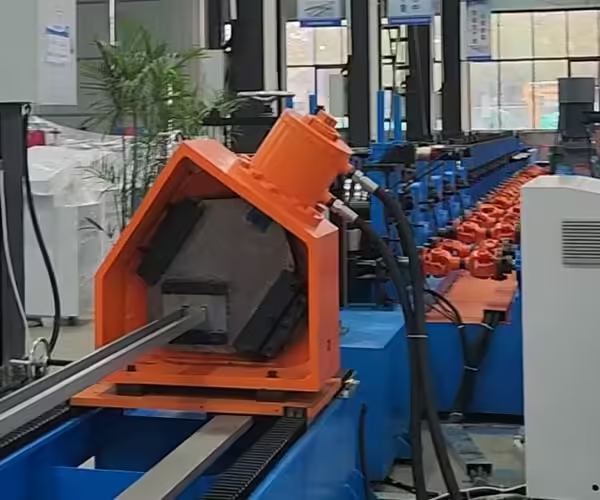
A C-channel solar bracket normally includes a web, two flanges, and optional lips. The lips can add local stiffness and may also support particular nuts, clamps, or connection systems.
The detailed cross-section can vary considerably between mounting-system manufacturers.
Lipped C Profiles
A lipped C profile has short return edges at the ends of the flanges. These features may increase forming complexity because the lips and main flanges must be produced in a controlled sequence.
Roll Forming Considerations
The roll design must prevent edge waves, twisting, excessive springback, and damage to the protective coating. Small lip dimensions can be particularly sensitive to material variation and tooling alignment.
Slotted C Channels
Slots allow installers to adjust the position of bolts, clamps, and connecting plates. Their length, width, spacing, and orientation should be defined in the product drawing.
If several slot patterns are required, the punching control system must store and execute different programs without creating unnecessary changeover time.
Adjustable C-Channel Production
Some manufacturers require several channel widths or flange heights. An adjustable solar mounting bracket roll forming machine may reduce the need for complete roll replacement when product dimensions change.
However, “adjustable” does not mean that every profile can be produced with one tooling set. Buyers must confirm the exact adjustment range and identify which dimensions still require tooling changes.
Understanding U-Channel Solar Brackets

A U-channel generally has a central web and two open flanges. Its relatively simple geometry can make it suitable for rails, purlins, supports, connecting members, and other mounting-system components.
The absence of return lips may simplify forming, but dimensional accuracy remains important.
Basic U Profiles
A basic U profile can be produced from galvanized steel, coated steel, or another specified metal. The required forming stations depend on material strength, thickness, channel depth, flange height, and corner radius.
Perforated U Channels
Perforated U channels contain holes or slots for installation and adjustment. The punching system must coordinate with the feeding system so that every feature remains in the correct position relative to the cut ends.
End-Distance Control
Even if the repeated hole spacing is correct, an inaccurate cutting reference can leave the first or last hole too close to the profile end. Punching and cutting must therefore operate as one coordinated process.
U Profiles with Reinforcing Features
Some designs include ribs, grooves, beads, or stiffening features in the web or flange. These details may increase rigidity or support a specific assembly method.
They also affect tooling design and forming sequence. The machine supplier should receive the complete profile drawing before preparing a quotation.
Which Profile Is Easier to Manufacture?
Simple U profiles generally require fewer forming steps than complex lipped C profiles. However, production difficulty depends on more than the name of the cross-section.
A deep U profile made from high-strength, thick steel may be more demanding than a small C profile made from lighter material.
Factors That Increase Forming Difficulty
The following features can make either profile more difficult to produce:
- High-strength steel
- Thick strip material
- Narrow or deep channels
- Small corner radii
- Long return lips
- Asymmetrical cross-sections
- Closely spaced holes
- Embossed or ribbed surfaces
- Strict twist and straightness limits
- Damage-sensitive coatings
Springback
Springback occurs when the material partially returns toward its original shape after leaving the rolls. Its effect varies according to material strength, thickness, bend radius, and profile geometry.
The roll tooling should compensate for predictable springback without causing excessive stress or coating damage.
Profile Twist
Twist can result from uneven forming force, incorrect roll alignment, inconsistent strip properties, or an asymmetrical hole pattern. It can make installation difficult even when individual cross-sectional dimensions appear correct.
Material Selection for Solar Mounting Profiles
The solar mounting bracket roll forming machine must be designed for the actual material used in production. Describing the material simply as “galvanized steel” is not sufficient for accurate machine design.
The supplier should receive the relevant grade, yield strength, tensile strength, coating type, thickness range, and strip-width tolerance.
Galvanized Steel
Galvanized steel is widely used for outdoor structural components because the zinc coating provides corrosion protection. During roll forming, tooling surfaces and material handling should be controlled to reduce scratching or flaking.
Pre-Coated Steel
Some profiles are produced from pre-coated material. Surface appearance and coating integrity may be important acceptance criteria, especially when the formed component will not receive additional treatment.
Tooling Surface Quality
Smooth roll surfaces, clean material paths, correct roll clearance, and controlled strip guidance help protect coated material. Dirt or metal particles trapped between the strip and rolls can create continuous surface marks.
High-Strength Steel
High-strength material may allow a mounting-system designer to achieve specific performance with a relatively thin section. However, it generally requires greater forming force and more careful springback control.
Motor power, shaft diameter, frame rigidity, roll material, and the number of forming stations should be evaluated accordingly.
Aluminum and Other Materials
Some solar mounting components are made from aluminum or other corrosion-resistant materials. These materials have forming behaviors that differ from carbon steel.
A production line intended for multiple materials should be reviewed for roll clearance, surface protection, forming sequence, and cutting compatibility.
Pre-Punching vs Post-Punching
Punching position is one of the most important decisions when configuring a solar mounting bracket roll forming machine. Both pre-punching and post-punching systems can be suitable when correctly designed.
The decision depends on hole patterns, production speed, profile shape, positional tolerance, tool access, and line layout.
Pre-Punching Before Roll Forming
In a pre-punching system, holes and slots are made while the strip is still flat. Flat strip is easier to support, and the punching die can access the material without interference from the formed flanges.
Pre-punching is commonly used for repeated holes and slots in solar mounting profiles.
Advantages of Pre-Punching
- Easier die access
- Convenient processing of several hole shapes
- Stable support for flat strip
- Suitable for integrated servo feeding
- Potentially simpler punching-tool construction
Points to Control
The roll forming process may slightly affect the final relationship between holes and profile dimensions. Feeding accuracy, strip movement, forming deformation, and cutting reference must be coordinated.
Post-Punching After Roll Forming
Post-punching creates holes after the profile has reached or approached its final shape. This may help position certain holes relative to finished-profile features.
However, the formed cross-section can restrict die access and require specialized support tooling.
Advantages of Post-Punching
- Hole location can reference the formed profile
- Suitable for some side or flange features
- Can support selected custom processing requirements
Points to Control
The profile must be supported during punching to prevent deformation. Punching speed and die movement may also limit total production speed.
Stop-to-Punch vs Flying Punching
A stop-to-punch system pauses strip movement during the punching cycle. It may offer a simpler control method but creates intermittent production.
A flying punching system synchronizes with moving material and can support higher continuous output.
Stop-to-Punch System
This system may be appropriate when production speed is moderate, hole patterns are complex, or investment cost must be controlled.
The buyer should calculate real output using the complete punching cycle rather than the forming machine’s maximum speed.
Flying Punching System
Flying punching can reduce stops and improve continuous production. It requires accurate motion synchronization and a control system capable of coordinating material position with punching movement.
When Higher Automation Creates Value
Flying punching is most valuable when order volume is high enough to justify the added equipment and control complexity. It should not be selected only because it appears more advanced.
Main Components of a Photovoltaic Bracket Production Line
A complete production line contains more than the roll forming section. Every component must support the required material, profile range, and production target.
Hydraulic or Mechanical Uncoiler
The uncoiler supports and feeds the metal coil. It should be selected according to coil width, inner diameter, outer diameter, and maximum weight.
For heavier coils or continuous production, hydraulic expansion and powered rotation can reduce manual handling.
Leveling Unit
The leveling unit helps correct coil set and prepares the strip for accurate feeding and punching. Poor leveling can contribute to unstable hole positions and profile deformation.
Servo Feeding System
Servo feeding controls the length of material entering the punching or cutting section. Its accuracy directly affects hole spacing and finished-product length.
Punching Press
The punching press creates holes, slots, notches, or other required features. Its capacity must be based on material strength, thickness, total cutting perimeter, and number of simultaneous holes.
Roll Forming Unit
This section contains the frame, shafts, rolls, bearings, transmission, and adjustment mechanisms. It performs the gradual bending sequence that creates the final profile.
Cutting System
The cutting system may use a pre-cut, post-cut, saw, or die-based configuration. The correct method depends on profile shape, edge-quality requirement, speed, and tolerance.
Run-Out and Collection System
Finished profiles must be safely supported and removed from the cutting area. Automatic stacking may be useful for long profiles or high-volume production.
Fixed Tooling vs Adjustable Roll Forming Machine
A fixed-tooling machine is designed around a defined profile or narrow product family. An adjustable machine allows selected dimensions to change through mechanical or servo-controlled adjustments.
The right choice depends on order volume and product diversity.
| Selection factor | Fixed-tooling machine | Adjustable machine |
|---|---|---|
| Product variety | Best for stable, repeated profiles | Better for several related sizes |
| Initial setup | Relatively straightforward | Requires careful range definition |
| Changeover | May require roll replacement | Some sizes can change by adjustment |
| Tooling cost | Separate tooling may be needed | May reduce the number of complete roll sets |
| Production stability | Strong for dedicated high-volume production | Depends on adjustment accuracy |
| Operator requirements | Standard setup skills | Additional parameter and adjustment control |
| Best application | Large orders of consistent profiles | Flexible or multi-size production |
An adjustable solar mounting bracket roll forming machine should be evaluated using the actual profile range. Buyers should ask which dimensions are automatically adjusted, manually adjusted, or fixed by tooling.
How Fast Should a Solar Bracket Forming Line Run?
Production speed should be measured by qualified finished profiles rather than the fastest movement of the forming section. Punching, cutting, coil changes, size adjustments, and inspections all influence real capacity.
The machine should maintain the required dimensions and surface quality at the agreed working speed.
Mechanical Forming Speed
This is the speed at which the forming section can move material under suitable conditions. It may not include stops for punching or cutting.
Integrated Line Speed
Integrated speed reflects the relationship between feeding, punching, forming, cutting, and collection. It provides a more realistic basis for production planning.
Saleable Output
Saleable output excludes setup pieces, coil ends, incorrectly punched sections, dimensional rejects, and profiles with damaged coatings.
Ask for a Capacity Matrix
The supplier should estimate stable output for representative combinations of:
- Profile type
- Material grade
- Strip thickness
- Finished length
- Hole pattern
- Punching method
- Cutting method
Important Profile Quality Checks
Finished photovoltaic brackets should be inspected against the approved drawing and purchase specification. Visual appearance alone cannot confirm whether the profile is suitable for assembly.
Cross-Sectional Dimensions
Check web width, flange height, lip length, corner radius, and overall profile dimensions. Measurements should be taken at defined points and recorded consistently.
Hole and Slot Position
Verify hole diameter, slot length, slot width, center distance, orientation, and distance from the cut end.
Straightness and Twist
Long solar profiles can develop bow, camber, or twist. These conditions can cause alignment problems during installation.
Cut Length and End Quality
Finished length must remain within the agreed tolerance. Cut ends should also be evaluated for burrs, deformation, and squareness.
Coating Condition
Inspect the surface for scratches, roll marks, flaking, and exposed substrate. The allowable condition should be agreed upon before production.
How to Choose the Right Solar Mounting Bracket Roll Forming Machine
Begin by preparing a complete product file. A supplier cannot accurately configure the line using only a profile photo or approximate dimensions.
Submit the Finished Profile Drawing
The drawing should clearly show:
- C, U, Z, or customized cross-section
- Web, flange, and lip dimensions
- Corner radii
- Material thickness
- Hole and slot patterns
- Finished profile length
- Dimensional tolerances
- Straightness and twist requirements
Provide Complete Material Data
Include:
- Material standard and grade
- Yield and tensile strength
- Thickness range
- Strip-width tolerance
- Surface coating
- Coil inner and outer diameter
- Maximum coil weight
Define Production Requirements
The supplier should know:
- Required pieces or meters per shift
- Main profile sizes
- Average order quantity
- Number of daily changeovers
- Expected annual output
- Available operators
- Required level of automation
Confirm Factory Conditions
Provide the available voltage, frequency, phase, floor area, building height, lifting capacity, and foundation conditions. These details influence line layout and installation planning.
Jinbolida’s solar photovoltaic bracket forming equipment can be customized around different profile and production requirements.
Factory Acceptance Test Checklist
A factory acceptance test should demonstrate that the completed production line can manufacture the agreed profile before shipment.
The acceptance document should define the test material, profile drawing, operating speed, measurement methods, and pass criteria.
Verify the Complete Production Cycle
The test should include:
- Coil or sample-strip feeding
- Leveling
- Servo positioning
- Hole punching
- Roll forming
- Cutting
- Product collection
- Finished-profile inspection
Measure Representative Products
Do not inspect only the first acceptable sample. Produce enough profiles to evaluate process stability, repeated hole position, cutting consistency, and surface condition.
Test More Than One Size
If the machine is sold as adjustable or multi-profile, the acceptance test should include representative products from different parts of the agreed range.
Record Changeover Time
For buyers producing multiple bracket specifications, document the time and steps required to change profile dimensions or tooling. This reveals whether the machine can meet the planned production schedule.
Common Purchasing Mistakes
Several avoidable mistakes can lead to delayed installation, poor profile quality, or lower-than-expected output.
Ordering Before the Product Drawing Is Final
Small changes to flange height, lip angle, hole location, or corner radius can require tooling modifications. Finalize the approved product range before machine manufacturing begins.
Comparing Only the Machine Price
One quotation may include punching dies, roll tooling, an uncoiler, and automatic stacking, while another excludes them. Compare the complete line scope and technical performance.
Ignoring Material Strength
Two coils with the same thickness may require different forming force because their mechanical properties are different.
Assuming One Tooling Set Makes Every Profile
Similar-looking C and U profiles may still require different roll sets or forming stations. Request a profile-by-profile tooling list.
Focusing Only on Maximum Speed
The real output may be limited by punching frequency, finished length, cutting cycles, or product changes.
Failing to Protect the Coating
Tooling finish, roll clearance, material cleanliness, and handling methods should be considered when galvanized or pre-coated steel is used.
Conclusion
Choosing a solar mounting bracket roll forming machine begins with the finished bracket, not the machine catalog. C-shaped and U-shaped profiles have different forming and installation characteristics, and each product must be supported by an approved drawing and material specification.
Buyers should evaluate material strength, coating, profile range, hole pattern, punching method, roll tooling, forming capacity, cutting system, adjustment method, automation, and real production output. These factors determine whether the line can consistently produce qualified brackets.
Before placing an order, prepare a complete technical file and request a written line configuration. The supplier should explain how every stage—from coil loading to finished-profile collection—supports the required products.
You can review Jinbolida’s solar mounting production line and its broader profile processing equipment for related production solutions. To obtain a configuration based on your bracket drawings, materials, hole patterns, and capacity target, submit the project information through the contact page.
FAQ
What profiles can a solar mounting bracket roll forming machine produce?
Depending on its design and tooling, the machine may produce C-shaped, U-shaped, Z-shaped, lipped-channel, slotted-channel, or customized photovoltaic mounting profiles.
Can one machine produce both C and U channels?
It may be possible with interchangeable or specially designed adjustable tooling. The supplier must evaluate the exact drawings, material range, and required changeover method.
Should holes be punched before or after roll forming?
Pre-punching is convenient because the strip is flat and easy to support. Post-punching may be useful when hole locations must reference the finished profile. The best method depends on the product drawing and required accuracy.
Can the machine process galvanized steel?
Yes, if the tooling and line are designed for the specified galvanized steel grade, thickness, and coating. Roll surfaces and strip handling should minimize coating damage.
How many forming stations are required?
The number depends on profile complexity, material properties, thickness, corner radius, required speed, and tolerance. More stations are not automatically better unless they support a suitable forming sequence.
What is the difference between fixed and adjustable machines?
A fixed machine is optimized for a defined profile, while an adjustable machine can change selected profile dimensions. Buyers should confirm the real adjustment range before ordering.
How is production speed calculated?
Real speed should include punching, forming, cutting, and material-handling cycles. Calculate saleable output rather than relying only on the forming section’s maximum speed.
What information is required for a machine quotation?
Provide profile drawings, material grades, thicknesses, hole patterns, finished lengths, tolerance requirements, coil data, production targets, power conditions, and factory layout.
Can one line produce solar brackets of different lengths?
Yes. A programmed feeding and cutting system can normally produce different lengths within its designed range. Hole patterns may also be changed through the control program when the punching configuration supports them.
How should the machine be tested before delivery?
Use representative production material and inspect profile dimensions, hole positions, straightness, twist, cut length, surface quality, speed, and changeover performance.
If you enjoyed this article on Jinbolida’s smart manufacturing and digital factory expertise, follow us for more insights and updates:
- 📘 Facebook: Stay tuned for our latest smart production line projects → Facebook
- 📱 WhatsApp: Contact us anytime for custom production solutions → Chat Now
- ▶️ YouTube: Watch our automated line demos and real-world applications → YouTube
Let’s keep innovating and shaping the future of smart manufacturing — together!
 English
  Arabic
  Russian
  Spanish
  French