
Roll Forming Machine FAT: What Buyers Should Test
Table of Contents
Introduction

A new roll forming production line can look impressive during a factory visit. Motors run, hydraulic cylinders move, the PLC responds, and the rollers rotate smoothly. But none of these observations alone proves that the equipment can repeatedly manufacture the buyer’s actual profile.
This is why roll forming machine FAT—Factory Acceptance Testing—should focus on finished-product performance rather than machine movement alone.
A meaningful FAT should answer practical questions such as:
- Can the machine process the specified material?
- Does the finished profile match the approved drawing?
- Are punched holes and slots correctly positioned?
- Is cut length stable?
- Does the profile remain straight after cutting?
- Can the line reach the agreed production condition?
- Can different product recipes be changed correctly?
- Are safety functions and alarms working?
- Can several consecutive products maintain repeatable quality?
For buyers, FAT is one of the last opportunities to verify these requirements before the production line leaves the supplier’s factory.
JBLDIE’s Roll Forming Machine Guide also emphasizes evaluating a forming system from coil loading through finished-profile inspection rather than judging only the forming rolls themselves.
The strongest FAT therefore begins with the finished product and works backward through every process needed to manufacture it.
What Is a Roll Forming Machine FAT?
A roll forming machine FAT is a structured test conducted at the equipment manufacturer’s facility before shipment.
Its purpose is to verify whether the machine performs the functions and manufacturing requirements agreed between supplier and buyer.
Depending on the production line, FAT may include:
coil loading → decoiling → leveling → servo feeding → punching → roll forming → straightening → cutting → unloading → stacking
The test can also verify:
- electrical control,
- PLC/HMI operation,
- sensors,
- servo systems,
- hydraulic systems,
- pneumatic systems,
- alarm logic,
- emergency stops,
- guards,
- interlocks,
- production recipes,
- and documentation.
However, the most important result is still the finished component.
A machine can complete every automatic movement successfully while producing a profile outside the required dimensions.
That is why FAT should combine machine-function testing and product-quality testing.
FAT Should Start Before the Machine Is Built
One of the biggest FAT mistakes is discussing acceptance criteria only after the production line is already complete.
By that point, buyer and supplier may have different expectations.
The buyer may expect:
- a particular line speed,
- a specific profile tolerance,
- one-button changeover,
- or a certain punching accuracy.
The supplier may have designed the machine around different assumptions.
FAT requirements should therefore be agreed during the technical-confirmation stage.
The technical package should define:
- profile drawings,
- material grade,
- thickness range,
- coil dimensions,
- punching drawings,
- cut lengths,
- production requirements,
- tolerance requirements,
- surface-quality requirements,
- automation scope,
- and acceptance method.
FAT then becomes a verification of agreed requirements rather than a negotiation at the end of manufacturing.
What Should Be Included in the FAT Document?
A useful FAT document can separate requirements into several groups.
| FAT Area | What Should Be Verified |
|---|---|
| Product | Profile geometry and dimensions |
| Material | Agreed grade and thickness |
| Punching | Hole/slot size and position |
| Cutting | Length and end condition |
| Straightness | Bow, camber and twist |
| Surface | Scratches and forming marks |
| Production | Agreed operating condition |
| Repeatability | Multiple consecutive products |
| Automation | Sequence, recipes and sensors |
| Safety | Guards, interlocks and E-stops |
| Alarms | Fault detection and recovery |
| Changeover | Agreed product-switch procedure |
| Documentation | Drawings, manuals and records |
Each item should have a clear acceptance method where necessary.
Instead of writing:
“Profile accuracy must be good.”
write:
“Measure the specified dimensions according to drawing revision X using the agreed datum and inspection method.”
Clear acceptance criteria reduce disputes during FAT.
Test the Actual Product, Not a Convenient Sample
A common FAT shortcut is to use a simple profile because it is easy to demonstrate.
That may not represent the buyer’s real production requirement.
Suppose the line was selected to produce:
- lipped C channels,
- 2.5 mm galvanized high-strength steel,
- multiple elongated slots,
- several product lengths,
- and automatic stacking.
Testing only a thin, unpunched U-channel gives limited evidence about actual capability.
The test product should represent a meaningful production condition.
Where several profiles are included in the machine scope, FAT should preferably include at least one of the more demanding products.
A useful representative profile may be:
- relatively thick,
- high strength,
- complex in geometry,
- heavily punched,
- or difficult to change over.
Testing only the easiest product can hide limitations that appear later at the buyer’s factory.
Use Representative Production Material
Material behavior directly affects roll forming.
Important variables include:
- yield strength,
- tensile strength,
- thickness,
- strip width,
- coating,
- surface condition,
- and coil condition.
A machine designed for higher-strength steel should ideally be tested with the agreed grade or a genuinely representative material where practical.
Testing a high-strength profile using much softer steel can hide:
- springback,
- forming-force requirements,
- shaft deflection,
- punching load,
- cutting load,
- and straightening difficulty.
Likewise, testing only thin sheet provides limited evidence about the upper end of the agreed material range.
Buyers should therefore define FAT material before the test date.
Do Not Test Only One Piece
A single good profile does not prove that a roll forming line is stable.
One piece may happen to fall within tolerance after several manual adjustments.
The more important question is whether the next pieces remain consistent.
A better FAT produces multiple consecutive profiles after the machine has reached the agreed operating condition.
For example, the inspection plan might include:
- first qualified piece,
- another early production piece,
- a middle sample,
- and later samples during continuous running.
The exact sampling plan depends on the project.
The objective is to test repeatability, not just one successful result.
Check the Finished Profile After It Leaves the Machine
A roll formed profile may look correct while it is still restrained by the rollers.
After cutting, residual stress can be released.
The finished component can then:
- spring open,
- bow,
- camber,
- twist,
- develop end flare,
- or change in cross-sectional geometry.
For this reason, FAT measurements should be performed on the finished unloaded product where appropriate.
Do not approve profile geometry based only on what the section looks like inside the final forming stand.
The product that leaves the machine is the product that matters.
Which Profile Dimensions Should Be Measured?
The exact dimensions depend on the finished drawing.
Common checks can include:
- overall width,
- overall height,
- web width,
- flange height,
- lip length,
- bend angle,
- inside radius,
- channel opening,
- rib height,
- rib spacing,
- diagonal dimensions,
- hole position,
- slot position,
- finished length,
- straightness,
- camber,
- and twist.
Critical dimensions should be identified before FAT.
Not every dimension has equal functional importance.
For example, on a solar C-channel, opening width and hole position may directly affect connector compatibility.
On a square tube, width, height, diagonal relationship, corner radius, and straightness may matter more.
The inspection plan should follow the actual application.
Measurement Instruments Should Be Suitable for the Required Tolerance
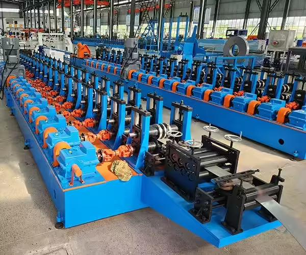
FAT results are only useful when the measurement method is reliable.
If a tolerance is relatively tight, using an unsuitable or poorly controlled measuring instrument can make the result questionable.
Depending on the profile, inspection tools may include:
- calipers,
- micrometers,
- height gauges,
- angle gauges,
- tape measures,
- straightedges,
- squares,
- dedicated profile gauges,
- and other dimensional inspection equipment.
Where measurement traceability is required by the buyer’s quality system, the inspection equipment should be controlled accordingly.
The U.S. National Institute of Standards and Technology explains metrological traceability as a measurement result being related to a reference through a documented, unbroken chain of calibrations, with each step contributing to measurement uncertainty.
This does not mean every FAT requires direct NIST calibration. It means buyers should agree on appropriate measurement control for the acceptance decision.
Agree on the Measurement Datum
Two people can measure the same profile and obtain different results if they reference different points.
For example, flange height might be measured:
- from the outer surface,
- from an internal tangent,
- from a web datum,
- or from another defined reference.
Likewise, hole position could be measured from:
- one cut end,
- profile centerline,
- one side edge,
- or the center of another hole.
The drawing and FAT procedure should define the reference.
This is especially important for profiles containing:
- bends,
- radii,
- asymmetric geometry,
- and complex punching patterns.
A good FAT removes ambiguity from the inspection method.
Check Punching Accuracy on the Finished Product
When the production line includes punching, buyers should inspect more than whether the punch moves correctly.
Check:
- round-hole diameter,
- slot width,
- slot length,
- local pitch,
- cumulative hole position,
- transverse position,
- first-hole distance,
- last-hole distance,
- and hole-to-bend relationship.
Pre-punched features may move relative to the final profile geometry during forming.
This is why hole position should be checked on the finished section.
For long profiles containing many repeated holes or slots, cumulative accuracy deserves special attention.
A small feed error repeated many times can become more visible between:
first hole → final hole.
Do Not Judge Punching Accuracy From Servo Resolution Alone
A servo motor may have excellent command resolution.
That does not automatically mean the actual strip moves with identical accuracy.
Real material positioning can also depend on:
- feeder slip,
- roller pressure,
- upstream tension,
- encoder condition,
- material surface,
- guide resistance,
- and mechanical wear.
During FAT, compare programmed positions with actual finished-product measurements.
The purpose of the test is to verify the complete system rather than one component’s specification.
Cutting Length Should Be Tested Across Multiple Pieces
A production line may be programmed to cut six-meter profiles.
The important question is whether finished parts consistently match the required length.
Measure several consecutive components.
If length varies, investigate:
- encoder or measuring wheel,
- servo tracking,
- material slip,
- cutter synchronization,
- control timing,
- and actual line movement.
Also inspect the relationship between cutting and punched features.
For example, a part may have the correct overall length but the last hole may be too close to the end if punching and cutting references are not coordinated.
Inspect the Cut End
Finished length is only part of cut quality.
The end of the profile should also be checked for:
- crushing,
- distortion,
- burr,
- flare,
- coating damage,
- and incomplete cutting.
Complex roll formed sections require suitable support during cutting.
A cutter that produces the correct length but deforms the profile end can still create downstream assembly problems.
This becomes particularly important for:
- lipped C channels,
- deep structural profiles,
- high-strength steel,
- and thin appearance-sensitive material.
Straightness Must Be Measured on a Long Enough Product
Short samples can hide long-profile problems.
A C-channel may look straight over one meter but develop obvious bow or twist over six meters.
FAT should therefore use representative finished lengths.
Depending on product requirements, evaluate:
- longitudinal bow,
- lateral camber,
- twist,
- end flare,
- and overall straightness.
The measurement method should also be agreed in advance.
For long components, the supporting surface can influence how the profile appears, so inspection conditions should remain consistent.
Check Surface Quality Under Real Forming Conditions
Surface quality is especially important when processing:
- galvanized steel,
- pre-painted steel,
- stainless steel,
- aluminum,
- or other visible/coated materials.
Inspect the finished profile for:
- repeating roll marks,
- scratches,
- dents,
- guide lines,
- feeder marks,
- punching debris marks,
- and handling damage.
The pattern often indicates the source.
A repeating defect may correspond with one rotating roll.
A continuous line may come from a fixed guide.
Random damage may originate from debris or downstream handling.
FAT should inspect the whole material path rather than only the forming rolls.
Run the Machine at a Representative Production Speed
Some machines can produce excellent profiles during very slow trial operation but become unstable as speed increases.
Potential problems that appear at higher speed include:
- strip tracking,
- vibration,
- feeder instability,
- punching synchronization,
- cutter timing,
- profile handling,
- sensor response,
- and stacking problems.
FAT should therefore include production at an agreed representative condition.
This does not always need to mean maximum theoretical speed.
The meaningful question is:
At what speed can the complete line repeatedly produce qualified profiles?
Usable production capacity is more important than a short maximum-speed demonstration.
Maximum Speed Is Not the Same as Qualified Output
Suppose a forming machine can mechanically run at 40 m/min.
The complete line may still operate more slowly because:
- punching requires repeated stops,
- servo feeding needs positioning time,
- cutting interrupts material movement,
- unloading cannot keep pace,
- or product quality becomes unstable.
FAT should therefore distinguish between:
forming speed
and
qualified finished-product capacity.
For equipment covering multiple operations, the slowest repeated process often determines practical output.
This distinction is particularly important in heavily punched photovoltaic bracket lines.
Test Continuous Running, Not Only Short Demonstrations
A five-minute run may not reveal problems that appear after the equipment operates for longer periods.
Continuous testing can reveal:
- bearing temperature,
- hydraulic temperature,
- lubrication issues,
- fastener loosening,
- sensor instability,
- dimensional drift,
- tooling movement,
- cut-length drift,
- and accumulation problems in downstream handling.
The appropriate duration depends on the project.
The purpose is to run long enough to demonstrate that the line remains stable rather than producing only a few demonstration pieces.
Record Quality During the Run
Do not measure only before and after continuous testing.
Take samples during production.
A simple FAT record may include:
| Sample | Profile Dimension | Hole Position | Length | Straightness | Surface |
|---|---|---|---|---|---|
| Start | Pass/Fail | Pass/Fail | Pass/Fail | Pass/Fail | Pass/Fail |
| Mid-run | Pass/Fail | Pass/Fail | Pass/Fail | Pass/Fail | Pass/Fail |
| Later run | Pass/Fail | Pass/Fail | Pass/Fail | Pass/Fail | Pass/Fail |
| Final | Pass/Fail | Pass/Fail | Pass/Fail | Pass/Fail | Pass/Fail |
More detailed dimensional values can be recorded where required.
This helps identify drift that a simple final check might miss.
Test Changeover When Multi-Profile Production Is Part of the Scope
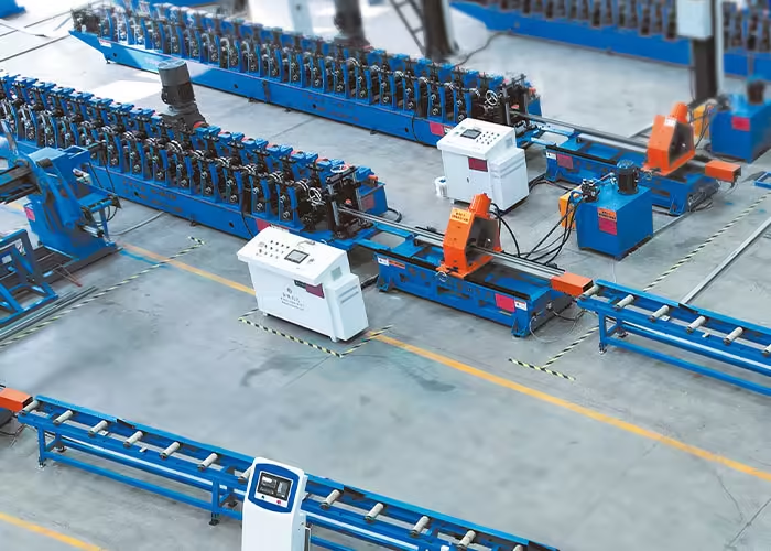
If the machine is sold specifically for producing multiple sizes or profiles, FAT should verify the changeover concept where practical.
The test should not measure only how quickly one button is pressed.
A realistic changeover includes:
last qualified Product A → adjustment/tooling change → trial → first qualified Product B
Check:
- mechanical adjustment,
- guide changes,
- roll positioning,
- punching recipe,
- cut length,
- PLC selection,
- and first-piece verification.
For a flexible roll forming system, repeatability after changeover can be as important as raw production speed.
Test Stored Product Recipes
Modern production lines can store recipes for:
- servo-feed distances,
- punching sequences,
- cut lengths,
- motorized adjustments,
- line speed,
- quantities,
- and other settings.
During FAT, select different product recipes and verify that the physical production result matches the intended program.
A recipe can load correctly on the HMI while the mechanical setup remains wrong.
Digital and mechanical configuration should therefore be tested together.
Verify Sensors and Interlocks
Automatic lines depend on sensors to confirm machine conditions.
Possible sensors include:
- material presence,
- coil loop,
- feeder position,
- punch position,
- cutter position,
- profile arrival,
- unloading position,
- stack condition,
- and safety access.
FAT should test whether the control system responds correctly when expected conditions are not met.
For example:
- What happens if material is absent?
- What happens if the punch does not return?
- What happens if the cutter remains out of position?
- What happens if the unloading station is occupied?
A good automated line should not simply work when everything goes right.
It should also identify abnormal conditions clearly.
Alarm Messages Should Help the Operator
An alarm such as:
ERROR 1027
provides limited value if the operator cannot determine what it means.
More useful diagnostics identify the affected system or condition.
FAT should therefore verify:
- alarm display,
- machine response,
- recovery procedure,
- alarm history,
- and restart sequence.
This is especially important for complex lines integrating:
- punching,
- servo feeding,
- cutting,
- robotics,
- and stacking.
Good fault diagnostics can reduce future troubleshooting time.
Emergency Stops Need to Be Tested
Emergency-stop devices should be tested according to the machine design and applicable requirements.
The test should verify that activating an E-stop creates the intended machine response.
Buyers should also understand:
- which equipment is stopped,
- how stored energy is handled,
- what remains energized,
- and what restart procedure is required.
These points need to be considered as part of the complete safety design rather than as a single red button test.
Machine Guarding Should Be Included in FAT
Roll forming lines contain several potential hazard zones, including:
- rotating shafts,
- roll in-running nip points,
- decoilers,
- punching systems,
- cutting stations,
- transfer devices,
- and moving finished products.
OSHA’s general machine-guarding requirements require guarding methods to protect workers from hazards such as points of operation, ingoing nip points, rotating parts, flying chips, and sparks; the regulation specifically identifies forming rolls among machines typically requiring point-of-operation guarding.
Applicable legal requirements vary by destination, machine design, and workplace, so FAT should verify the agreed safeguarding scope rather than assuming one universal configuration applies everywhere.
Test Guards and Interlocks Functionally
It is not enough that a guard is physically installed.
Where interlocks form part of the design, FAT should verify the intended response.
For example:
- Does opening a protected access point stop the relevant motion?
- Can the machine restart unexpectedly when the guard is closed?
- Is reset required?
- Does the HMI show which safety condition is active?
The actual validation method depends on the control architecture and applicable standards.
The important point is that safeguarding should be tested as a functional system.
Verify Manual, Setup, and Automatic Modes
Many production lines have more than one operating mode.
These may include:
- manual/jog,
- setup,
- single cycle,
- automatic,
- maintenance-related functions,
- or other machine-specific modes.
FAT should confirm that each required mode behaves as intended.
The test should pay particular attention to transitions between modes.
For example, the machine should not unexpectedly begin automatic movement simply because an operator exits manual mode.
The control philosophy should be understandable to the people who will operate the equipment.
Test Power-Off and Restart Behavior
Buyers should understand what happens after:
- normal shutdown,
- emergency stop,
- temporary power loss,
- PLC restart,
- servo alarm,
- or hydraulic interruption.
Questions include:
- Does the machine retain the product recipe?
- Does it remember production count?
- Does material position need to be re-established?
- Can punching sequence resume correctly?
- Must the current part be removed?
- Does the machine restart from a safe condition?
These situations can occur during real factory operation.
FAT is a useful place to confirm the expected recovery logic.
Inspect the Electrical Cabinet
The electrical system should be reviewed together with the machine functions.
Depending on the project, buyers may verify:
- component identification,
- wire labeling,
- terminal labeling,
- cabinet ventilation,
- cable routing,
- PLC hardware,
- servo drives,
- safety components,
- documentation,
- and electrical drawings.
The objective is not simply appearance.
Clear labeling and documentation can make future maintenance and troubleshooting much easier.
Hydraulic and Pneumatic Systems Need Functional Checks
Lines containing punching, cutting, clamping, or other actuated equipment may use hydraulic or pneumatic systems.
FAT can check:
- pressure stability,
- leaks,
- cylinder operation,
- valve response,
- filtration,
- hose routing,
- and alarm functions.
Repeated operation during continuous testing can reveal issues that a single cylinder movement may not show.
Pressure should also remain consistent with the actual production process.
Verify Lubrication and Maintenance Access
A machine can pass its production test but still be difficult to maintain.
Buyers should inspect access to:
- bearings,
- forming rolls,
- shafts,
- guides,
- chains,
- gearboxes,
- lubrication points,
- punching dies,
- cutting tools,
- sensors,
- hydraulic components,
- and electrical cabinets.
Ask practical questions.
Can normal wear parts be reached without dismantling unrelated equipment?
Are lubrication points accessible?
Can rolls be cleaned?
Can punches be replaced?
FAT is one of the best times to review these details while the machine is fully assembled.
Documentation Is Part of FAT
A production line cannot be maintained effectively without usable technical information.
The documentation package can include:
- machine layout,
- electrical diagrams,
- hydraulic diagrams,
- pneumatic diagrams,
- tooling drawings where agreed,
- equipment manuals,
- maintenance instructions,
- lubrication information,
- PLC/HMI backup arrangements,
- spare-parts list,
- setup instructions,
- and acceptance records.
The exact package depends on the project.
Buyers should agree on required documentation before shipment rather than trying to collect missing information after installation.
Quality Management Context
FAT itself should be based on the contract and agreed technical specification rather than treating a generic quality standard as a machine-specific acceptance procedure.
However, the broader principles of controlled requirements, documented processes, verification, and continual improvement align with established quality-management practices.
The International Organization for Standardization describes ISO 9001 as a widely recognized quality-management-system standard focused on consistent processes, customer requirements, performance, and continual improvement.
ISO 9001 does not tell buyers exactly how to FAT a roll forming machine. The value here is the underlying principle: acceptance should be documented, measurable, and based on defined requirements rather than subjective impressions.
Verify Spare and Wear Parts
Before shipment, confirm the agreed spare-parts package.
Depending on the production line, this may include items such as:
- sensors,
- seals,
- blades,
- punching components,
- electrical parts,
- hydraulic components,
- belts,
- or other consumables and wearing items.
The exact list should follow the machine design.
Buyers should also understand which components are:
- normal wear parts,
- recommended commissioning spares,
- and long-term maintenance items.
This reduces confusion after installation.
FAT Should Include Operator Questions
A machine that only the supplier’s commissioning engineer can operate is not yet fully prepared for handover.
The buyer’s technical team should use FAT to understand:
- startup,
- shutdown,
- threading,
- product selection,
- parameter changes,
- alarm recovery,
- tool change,
- lubrication,
- basic troubleshooting,
- and maintenance access.
Training does not need to replace formal site commissioning.
But FAT should give the buyer enough familiarity to identify unclear controls or documentation before shipment.
Record Every FAT Issue
Not every issue found during FAT needs to stop the entire acceptance process.
It is useful to classify findings.
For example:
Critical
Directly prevents the agreed machine or product requirement from being achieved.
Major
Important function or quality issue requiring correction.
Minor
Does not prevent production but should be resolved or documented.
Observation
Potential improvement or clarification.
Each item can include:
- description,
- responsible party,
- corrective action,
- status,
- evidence,
- and closure date.
This creates a clear punch list instead of relying on verbal memory.
Retest Corrected Items
If a critical or important issue is corrected during FAT, verify the correction.
For example, if hole-position error is adjusted, produce additional parts and measure them again.
If a sensor problem is repaired, repeat the abnormal-condition test.
If a cutter is adjusted, verify both:
- finished length,
- and cut-end quality.
Closing an issue should mean demonstrating that the problem has been resolved.
Take Photos, Videos, and Measurement Records
FAT documentation can provide a valuable baseline for later installation.
Useful records include:
- finished-profile measurements,
- successful machine settings,
- sample photos,
- machine videos,
- electrical cabinet photos,
- tooling positions,
- HMI screens,
- and accepted product samples.
When the machine is later installed at the buyer’s factory, these records help answer:
Did the machine reproduce the condition demonstrated during FAT?
This makes FAT useful for site commissioning as well as shipment approval.
Keep Accepted Profile Samples
Where practical, both buyer and supplier can retain approved sample pieces from FAT.
These can later serve as physical references for:
- profile geometry,
- punching pattern,
- surface quality,
- cutting,
- and assembly.
A physical sample should not replace the drawing and measurement record.
It provides an additional comparison reference.
This is particularly useful for visually sensitive features that are difficult to describe in text alone.
FAT and Site Acceptance Are Not the Same
Passing FAT does not eliminate the need for site commissioning.
After shipment, the machine experiences:
- disassembly where required,
- transportation,
- unloading,
- repositioning,
- foundation installation,
- leveling,
- electrical connection,
- hydraulic connection,
- and local utilities.
These can affect machine condition.
The buyer should therefore distinguish between:
Factory Acceptance Testing
Verifies the equipment before shipment.
Site Installation and Commissioning
Verifies that the equipment has been installed and restored to the correct production condition.
The successful FAT result becomes an important reference for site commissioning.
Use the Same Product at FAT and Site Commissioning Where Practical
If possible, reproducing a representative FAT product during site commissioning makes troubleshooting easier.
The technical team can compare:
- profile dimensions,
- settings,
- material,
- hole positions,
- speed,
- and surface condition.
If the machine produced a qualified profile at the supplier’s factory but does not reproduce it after installation, the investigation can focus on:
- installation,
- leveling,
- centerline,
- utilities,
- material,
- or setup differences.
This is much easier than beginning without a known production baseline.
Common FAT Mistakes
Testing the Machine Without Material
This confirms movement but not manufacturing performance.
Using Material That Is Easier Than the Real Specification
This can hide forming, punching, cutting, and springback problems.
Producing Only One Sample
This does not demonstrate process repeatability.
Running Only at Very Low Speed
Some instability appears only near normal operating conditions.
Measuring Only Cross-Section
Punching, cutting, straightness, and surface condition can still be incorrect.
Ignoring Product Changeover
A flexible machine needs to demonstrate flexible production.
Testing Only Normal Operation
Faults, alarms, sensors, and recovery also matter.
Using Unclear Acceptance Criteria
Subjective requirements create disagreements.
Ignoring Documentation
Missing drawings or manuals become much harder to resolve after shipment.
Accepting Corrections Without Retesting
A repair should be verified through the affected machine function or finished product.
Roll Forming Machine FAT Checklist
| FAT Check | Buyer Should Verify |
|---|---|
| Profile drawing | Correct revision is being tested |
| Material | Correct grade, thickness and width |
| Decoiler | Coil loads and feeds correctly |
| Leveler | Strip condition remains stable |
| Servo feed | Programmed movement matches product |
| Punching | Holes and slots meet requirements |
| Forming | Finished cross-section meets drawing |
| Straightness | Bow, camber and twist acceptable |
| Cutting | Length and cut-end condition acceptable |
| Surface | No unacceptable process damage |
| Repeatability | Multiple parts remain consistent |
| Speed | Agreed production condition demonstrated |
| Continuous run | Machine remains stable |
| Changeover | Multi-product function demonstrated |
| PLC/HMI | Recipes and controls function |
| Sensors | Position signals work correctly |
| Alarms | Faults are identified clearly |
| E-stop | Required stopping response verified |
| Guarding | Agreed safety functions verified |
| Documentation | Technical package available |
| Training | Main operating procedures understood |
| Punch list | Open issues documented |
What Should Buyers Send Before FAT?
A buyer can make FAT significantly more effective by preparing information in advance.
Product Drawings
Provide the approved profile and punching drawings.
Acceptance Tolerances
Identify critical dimensions and allowable ranges.
Material Specification
Define grade, thickness, width, and coating.
Product Lengths
Select representative test lengths.
Punching Program
Identify demanding hole or slot patterns.
Production Condition
Define the operating speed or output condition to be tested.
Measurement Method
Agree on tools, datums, and sampling.
Changeover Requirement
Identify which second product should be demonstrated if applicable.
Safety Scope
Confirm agreed safeguarding and control functions.
Documentation List
Define which manuals, drawings, backups, and records should be available.
This preparation turns FAT into a structured engineering test rather than a factory tour.
Which JBLDIE Roll Forming Machines Should Use FAT?
FAT is relevant across different forming applications.
JBLDIE’s Forming Machine range includes roll forming and integrated production equipment for applications such as photovoltaic brackets, C/U/Z profiles, structural sections, punching systems, and automated production lines.
The exact FAT content should change according to the machine.
For example:
Solar Bracket Line
Focus heavily on profile geometry, slot position, cumulative hole accuracy, galvanized surfaces, cutting, and changeover.
Roofing Panel Line
Focus on panel width, rib geometry, edge wave, twist, surface marks, cutting, and long-panel handling.
Guardrail Line
Focus on deep forming geometry, punching, material strength, straightness, and finished length.
Steel Formwork Line
Focus on dimensional repeatability, punching, integrated downstream processing, and assembly-related dimensions.
A generic FAT form should therefore be adapted to the product being manufactured.
How Many Internal and External Links Should the Article Use?
For SEO purposes, links should support the reader rather than interrupt the article.
This article uses JBLDIE internal links to connect the FAT topic with:
- the broader roll forming technical guide,
- relevant forming-machine equipment,
- and the final technical contact page.
The external references are limited to independent, high-authority sources covering:
- measurement traceability,
- machine guarding,
- and quality-management principles.
This creates useful topical support without sending readers toward competing roll forming equipment suppliers.
Conclusion
A successful roll forming machine FAT should prove that the complete production line can manufacture the agreed finished product repeatedly under representative conditions.
The test should go beyond checking whether:
- motors rotate,
- cylinders move,
- the PLC starts,
- and the machine looks complete.
Buyers should verify real material, profile geometry, punching, cutting, straightness, surface quality, operating speed, repeatability, changeover, automation, alarms, safeguarding, documentation, and operator usability.
The most important FAT principle is simple:
Test the machine using the conditions that matter in actual production.
If the factory will process high-strength 2.5 mm galvanized steel, test representative material.
If the product contains dozens of slots, test the real punching pattern.
If multi-profile flexibility is important, perform a representative changeover.
If production capacity matters, verify qualified output rather than only maximum mechanical speed.
When acceptance criteria are defined before the machine is built and verified systematically before shipment, FAT becomes much more than a final inspection. It creates a documented production baseline that can support shipment approval, site commissioning, operator training, and future troubleshooting.
FAQ
What is roll forming machine FAT?
Roll forming machine FAT is Factory Acceptance Testing performed at the machine manufacturer’s facility before shipment. It verifies agreed machine functions and finished-product requirements using defined test procedures.
Should a roll forming machine FAT use actual production material?
Representative production material should be used where practical, especially when material grade, strength, thickness, coating, or springback significantly affects machine performance.
How many profiles should be produced during FAT?
There is no universal number. The test should produce enough consecutive finished components to demonstrate repeatability and, where required, include a continuous production run rather than only one sample.
What dimensions should be checked during roll forming FAT?
Typical checks include cross-sectional dimensions, bend angles, holes and slots, cumulative hole position, finished length, straightness, camber, twist, cut-end condition, and surface quality. The exact items should follow the approved product drawing.
Is FAT the same as site commissioning?
No. FAT verifies the equipment at the supplier’s factory before shipment. Site commissioning verifies that the machine has been correctly installed and can reproduce its accepted production condition after transportation and installation.
Preparing a Roll Forming Machine FAT?
The acceptance test should be built around your actual profile drawing, material, punching pattern, tolerance, finished length, speed, changeover requirements, and automation scope. Contact JBLDIE to discuss your roll forming production requirements and acceptance criteria.
 English
  Arabic
  Russian
  Spanish
  French