
Roll Forming Tooling Design: How It Affects Accuracy
Table of Contents
Introduction
Roll forming tooling design directly influences whether a metal profile can be produced with stable dimensions, accurate bend angles, consistent surface quality, and repeatable geometry. Even when the roll forming machine itself is mechanically sound, an unsuitable tooling layout can lead to twist, bow, edge wave, excessive springback, dimensional drift, or difficult machine setup.
A successful tooling design does much more than reproduce the final cross-section of a profile. It determines how a flat metal strip moves progressively from its original condition to the finished shape through a carefully controlled sequence of forming passes. Each roller station must perform the right amount of deformation while maintaining stable material flow and avoiding unnecessary longitudinal strain.
For manufacturers evaluating new profiles, roll forming tooling design should therefore begin with the finished component drawing, material characteristics, tolerances, punching requirements, and production process—not simply with the final profile shape. Jinbolida’s roll forming machine guide provides additional context on how tooling fits into the complete coil-to-profile production process.
What Is Roll Forming Tooling Design?

Roll forming tooling design is the engineering process used to determine how a flat strip will be progressively bent into a finished profile and how the individual rolls, shafts, guides, side rolls, straighteners, and related components will control that process.
The designer normally starts with the required final cross-section. From there, the profile is divided into a sequence of intermediate shapes, often called a forming progression or flower pattern. Each intermediate shape represents the profile condition at a particular forming stage.
The rolls are then designed around those stages.
This means the final tooling system needs to answer several questions at the same time. How many forming passes are necessary? Where should each bend begin? How quickly should the bend angle increase? Which areas of the strip require additional support? How will material thickness and springback affect the final angle? How will punched holes or slots behave as the profile is formed?
Roll-Kraft’s technical overview of basic roll form design similarly identifies the finished cross-section, estimated strip width, bend progression, tooling layout, guides, side rolls, and straightening devices as interconnected parts of the tooling design process.
Why Tooling Design Has Such a Large Effect on Profile Accuracy
A roll forming machine usually contains a sequence of forming stands rather than one tool that creates the complete profile immediately.
This progressive deformation is one of the main advantages of roll forming because it allows long, complex profiles to be produced continuously. However, it also means that errors can accumulate.
If an early stand moves material incorrectly, the following stands receive a profile that is already different from the intended forming progression. Later rollers may then force the material back toward the target geometry, introducing additional stress rather than solving the original problem.
A tooling design that distributes deformation correctly helps keep material flow stable throughout the machine. A poor progression may stretch one area of the strip more than another, cause flanges to become unstable, change bend locations, or increase residual stress in the finished profile.
For this reason, accuracy should be designed into the entire forming sequence rather than corrected only at the final roller stands.
The Finished Profile Drawing Comes First
Before rollers are designed, the finished part must be clearly defined.
The profile drawing should identify important dimensions such as overall width, height, flange dimensions, lip dimensions, bend angles, radii, hole locations, slots, embossments, and other functional features. Critical tolerances should also be distinguished from dimensions that allow greater variation.
This distinction matters because not every dimension has the same functional importance.
For example, a mounting channel may require accurate hole positions for assembly while allowing slightly more variation in a non-functional flange. Another structural profile may depend heavily on angle, width, and section geometry because those dimensions affect how it connects with other components.
Tooling decisions should reflect these priorities.
A designer who receives only a basic sketch without tolerance information has much less information for determining where forming accuracy must be concentrated.
Material Properties Must Be Considered Before Designing the Rolls
The same profile geometry can behave differently when produced from different materials.
Material thickness is one of the most obvious variables, but yield strength, tensile strength, elongation, hardness, coating condition, and surface requirements can also influence forming behavior.
A stronger material may resist bending more than a softer material. After leaving a forming roll, it may also recover more of its original shape through springback. If the tooling does not account for this behavior, the final bend angle can differ from the intended geometry.
Thickness variation can affect roll contact and final dimensions as well. A tooling set designed around one thickness should therefore be evaluated carefully when a wide thickness range is expected.
Surface condition is another important consideration. Galvanized, coated, stainless, or pre-painted materials may require tooling surfaces and contact conditions that reduce the risk of scratching or marking.
This is why accurate material specifications should be provided before tooling development begins.
How the Flower Pattern Controls the Forming Process
The flower pattern is one of the most important parts of roll forming tooling design.
It shows how the flat strip gradually changes shape from the first forming pass to the final profile.
Imagine a simple channel. The strip does not normally enter the first stand flat and leave immediately with two 90-degree flanges. Instead, those bends are developed progressively across several stations.
The exact progression depends on profile geometry, material, bend location, section depth, flange length, thickness, machine configuration, and other processing requirements.
A well-designed progression avoids forcing too much deformation into a single station. It also attempts to control differences in the longitudinal movement of different parts of the strip.
When too much forming occurs too quickly, the material may become unstable. Wide flanges can develop edge wave, the section may twist, or residual stress can build up along the profile.
Adding forming stations does not automatically guarantee better quality, however. The objective is not simply to maximize the number of passes. The objective is to select a progression that allows each stand to perform a useful and controlled part of the total deformation.
How the Number of Forming Passes Affects Accuracy
The number of forming passes influences both profile stability and tooling complexity.
Too few passes may force the strip through aggressive changes in a short distance. This can increase local strain and make difficult geometries harder to control.
Too many unnecessary passes can make the line longer and introduce additional tooling and setup requirements without creating a meaningful forming advantage.
The correct number therefore depends on the actual profile.
A relatively simple angle profile may need fewer stages than a deep channel with return lips, ribs, multiple bends, or asymmetric geometry. Profiles containing several closely spaced bends may also require greater control over the sequence in which those bends are introduced.
Material strength and thickness influence the decision as well.
The design question should therefore be:
How much deformation can each pass introduce while keeping material flow stable?
rather than:
How many roller stands should the machine have?
Bend Progression and Bend Location Must Work Together
Accurate roll forming requires control over both the amount of bending and the location of the bend.
If tooling begins bending the strip at the wrong position, later rollers may have difficulty moving the bend line back to the intended location. The finished profile can then show dimensional differences even if the final angle appears correct.
This becomes particularly important on profiles with several bends close together.
For example, a lipped channel may include a web, two main flanges, and return lips. The order and rate at which these elements are formed influence how the entire cross-section behaves.
The tooling designer must consider how one bend affects adjacent material and whether forming one feature too early could restrict the movement required for another feature later in the line.
Springback Must Be Designed Into the Tooling

Metal does not remain exactly at the shape imposed by the roller at the instant it leaves the roll gap.
Elastic recovery causes the material to move slightly back toward its original condition. This behavior is commonly called springback.
The amount of springback depends on several factors, including material strength, thickness, bend radius, angle, and forming history.
Roll forming tooling may therefore use controlled over-forming in selected stages so that after springback occurs, the profile moves closer to the required final geometry.
However, over-forming should not be treated as a universal correction.
If a profile angle is incorrect because the material is entering off-center or because a roller stand is misaligned, adding more over-form may introduce new problems. Effective compensation depends on identifying whether the deviation actually comes from predictable material behavior.
Roll Gap Influences Both Geometry and Material Flow
The relationship between upper and lower rolls affects how the tooling contacts and guides the material.
If the roll gap is inappropriate, the profile may not follow the intended forming path. Excessive contact pressure can also mark the surface, increase friction, accelerate tooling wear, or introduce unwanted deformation.
At the same time, insufficient control may allow the strip to move unpredictably within the roll set.
Roll gap therefore needs to correspond with the tooling design, material thickness, and purpose of each forming stand.
It is generally better to use tooling geometry to guide the material correctly than to rely on excessive pressure to force the profile into position.
Side Rolls and Guides Can Be Essential for Complex Profiles
Not every forming requirement can be controlled effectively by horizontal upper and lower rolls alone.
Side rolls may be used where the profile requires lateral support, vertical forming actions, flange control, or stabilization at particular stages. Entry guides help establish the strip position before it reaches the first forming stand.
These components may appear secondary compared with the main forming rolls, but their influence on repeatability can be significant.
If the strip enters the first pass at the wrong lateral position, every later forming stage begins from an incorrect reference point. Likewise, inadequate support in a difficult section of the profile can allow material to move away from the intended forming path.
Tooling design therefore needs to consider the complete guiding system rather than treating individual rolls in isolation.
Tooling Factors That Influence Profile Accuracy
| Tooling Factor | What It Controls | Possible Result if Incorrect |
|---|---|---|
| Flower pattern | Forming progression | Twist, wave, residual stress |
| Number of passes | Deformation per station | Over-forming or unstable forming |
| Bend location | Profile geometry | Incorrect flange or web dimensions |
| Roll geometry | Material path | Dimensional variation |
| Roll gap | Contact and material control | Marks, distortion, inconsistent shape |
| Side rolls | Lateral profile support | Flange instability or sideways movement |
| Entry guides | Strip centerline | Camber, twist, dimensional drift |
| Over-form compensation | Springback control | Incorrect bend angles |
| Tooling surface | Surface contact | Scratches or coating damage |
| Final calibration | Finished geometry | Poor dimensional consistency |
Tooling Design Becomes More Complex With Asymmetrical Profiles
Symmetrical profiles generally allow forming forces to be distributed more evenly across the strip. Asymmetrical profiles can be more challenging because the two sides may require different amounts of deformation.
One side may contain several bends while the other remains relatively flat. This creates different forming paths across the strip width.
If these differences are not controlled, the profile may naturally pull, rotate, bow, or twist during forming.
The tooling progression must therefore account for how forces develop across the entire section. Side support, forming order, pass spacing, and correction strategy may all become more important.
For highly asymmetrical profiles, successful tooling design depends on understanding not only the final dimensions but also how the material wants to move during every intermediate forming stage.
Punched Holes and Slots Must Be Considered During Tooling Design
Many roll formed profiles are not simply formed and cut. They may also contain holes, slots, embossments, notches, or connection features.
When punching occurs before forming, these features become part of the material that passes through the tooling.
Their location relative to bend lines therefore matters.
A slot positioned close to a bend may distort as the surrounding metal is formed. Hole spacing may also change slightly if the surrounding strip experiences longitudinal strain during the forming process.
This is particularly important for solar mounting profiles, steel structural profiles, brackets, and other components where holes need to align with downstream assemblies.
Tooling design and punching design should therefore be coordinated rather than developed independently.
Jinbolida’s forming machine solutions can integrate forming with feeding, punching, cutting, and related production operations according to the finished profile and required process sequence.
Tooling Design Should Consider Cutting From the Beginning
Cutting may occur before or after forming depending on the product and production-line configuration.
Pre-cut material changes the way individual blanks move through the forming stands because the material no longer has the same continuous-strip support.
Post-cutting allows continuous forming but requires the finished profile to be separated without damaging its cross-section.
For complex profiles, the cut-off tooling must match the geometry of the finished section. Poor support during cutting can deform the end of the part even when the roll forming process itself is stable.
This means tooling design should not stop at the final forming stand. The interaction between forming, straightening, cutting, and receiving needs to be evaluated as part of the complete production process.
Tooling Wear Gradually Changes the Original Design Condition
Even accurately designed tooling cannot maintain the original forming condition indefinitely without inspection.
Roll surfaces experience repeated material contact. Bearings, shafts, spacers, and adjustment mechanisms also operate continuously during production.
As tooling wears, effective roll geometry or roll position may gradually change. Bend locations can shift slightly, gaps can change, and surface conditions may deteriorate.
These changes often appear as gradual dimensional drift rather than an immediate major defect.
A useful maintenance approach is therefore to compare current profile measurements with established baseline measurements. If a critical dimension slowly changes across multiple production periods, tooling condition should be included in the investigation.
Tooling Design and Machine Alignment Cannot Be Separated
Good tooling installed on a poorly aligned machine may still produce poor results.
The tooling design assumes that shafts, stands, and rolls operate within the intended geometric relationship. If shafts are not parallel or a stand is positioned incorrectly, the actual forming condition no longer matches the design.
This is why tooling development and machine setup should be treated as connected engineering activities.
When a profile does not meet specification, changing the roller shape should not be the first response automatically. Engineers should first determine whether the problem comes from the tooling design, tooling installation, machine alignment, raw material, or operating setup.
Otherwise, tooling may be modified to compensate for a mechanical problem that should have been corrected elsewhere.
How Tooling Design Helps Reduce Roll Forming Defects
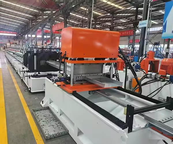
A large proportion of common roll forming problems are connected in some way with how deformation is introduced and controlled.
Edge wave may appear when flange material accumulates excessive longitudinal strain. Twist may develop when forces are not balanced across the section. Bow can result when different areas of the profile experience unequal length changes. Dimensional inconsistency can occur when bend positions or forming pressure are unstable.
Good tooling design reduces these risks by controlling the forming path before the machine enters continuous production.
This does not mean tooling can eliminate every process problem. Incoming coil variation, machine wear, setup errors, feeding instability, and operating conditions still influence the finished product.
However, a well-designed progression provides a much more stable foundation for troubleshooting and process control.
What Information Is Needed Before Designing Roll Form Tooling?
Before tooling development begins, the equipment and tooling team should understand the actual production requirement.
The most important starting point is the finished profile drawing. Material grade, thickness range, strip condition, coating, and surface requirements should also be defined as accurately as possible.
Hole patterns and punching sequences need to be considered when they are part of the finished component.
Production requirements such as profile length, cutting method, required dimensional accuracy, product variation, and changeover needs may influence tooling configuration as well.
If several related profiles need to run on the same machine, this should be identified early. Combination tooling or adjustable tooling requirements can affect the overall design approach.
Providing these details at the beginning is more effective than attempting to adapt generic tooling after the production line has already been defined.
How to Evaluate a Roll Forming Tooling Design
A tooling design should be evaluated by more than whether the final profile visually resembles the drawing.
Engineers should examine whether deformation is distributed logically between passes, whether critical bends remain controlled, whether material has sufficient support, and whether likely springback behavior has been considered.
The tooling should also suit the actual machine dimensions and shaft configuration.
During trial forming, profile measurements should be taken at selected stages rather than only after the final stand. This makes it easier to determine whether the strip is following the intended flower pattern.
The final evaluation should include dimensional accuracy, straightness, twist, surface condition, hole position where relevant, end condition after cutting, and repeatability across multiple samples.
A profile that can be produced correctly once is not enough. The purpose of good tooling design is to create a process capable of producing the required geometry consistently.
Conclusion
Roll forming tooling design is one of the most important factors affecting profile accuracy because it determines how deformation develops throughout the production line.
The finished profile drawing establishes the target geometry, but achieving that geometry requires a carefully planned forming progression. Material properties, bend locations, number of passes, roll geometry, roll gaps, guides, side rolls, springback, punching, cutting, and machine alignment all influence the result.
The best tooling design does not simply force the strip into its final shape. It controls material movement progressively so that each forming stand contributes the correct amount of deformation while minimizing unnecessary stress.
For manufacturers developing a new roll formed component, tooling should therefore be considered at the beginning of production-line planning. Accurate drawings, complete material information, realistic tolerance requirements, and clearly defined processing steps provide the foundation for more stable tooling development and more consistent finished profiles.
FAQ
What is roll forming tooling design?
Roll forming tooling design is the process of developing the roller geometry and forming sequence used to gradually transform flat metal strip into a specified cross-section. It includes the flower pattern, roll passes, guides, side rolls, compensation for springback, and other tooling elements.
How does tooling design affect roll forming accuracy?
Tooling determines where bends occur, how quickly they develop, how the material is supported, and how forming forces are distributed. Poor tooling design can contribute to twist, bow, edge wave, dimensional variation, and inconsistent bend angles.
How many roll forming passes are needed?
There is no universal number. The required number depends on profile complexity, material properties, thickness, bend geometry, section depth, tolerances, and machine configuration. The goal is to distribute deformation across enough stages to maintain stable material flow.
What is a flower pattern in roll forming?
A flower pattern shows the intermediate profile shapes between the initial flat strip and finished section. It allows designers to plan how bends will develop progressively through each roll forming station.
Can one set of roll forming tooling produce different profiles?
Some tooling can be designed for related profile sizes or adjustable configurations, but this depends on the differences between the finished sections, material range, machine structure, and accuracy requirements. Multi-profile requirements should be identified before tooling development begins.
Need Help With a Custom Roll Forming Profile?
A reliable production line starts with the finished profile, material, tolerance, punching pattern, cutting method, and required production process. If you are evaluating tooling or equipment for a new metal profile, contact Jinbolida to discuss your drawings and manufacturing requirements.
 English
  Arabic
  Russian
  Spanish
  French