
Solar Support Bracket Forming Machine: Complete Line Layout Guide
Table of Contents
Key Takeaways
- Design the production line around the finished bracket drawing and required output.
- Reserve separate areas for coil storage, loading, punching, forming, cutting, stacking, inspection, and finished-product storage.
- Identify the slowest repeated process before calculating the actual line capacity.
- Compare straight-line, U-shaped, and separated-cell layouts according to the available factory space.
- Provide enough maintenance access around the decoiler, roll former, punching dies, cutter, electrical cabinet, and hydraulic system.
- Include material flow, operator movement, forklifts, cranes, safety fences, and future expansion in the layout.
- Confirm the line layout through a factory acceptance test before shipment and a site acceptance test after installation.
A solar support bracket forming machine is not a single piece of equipment operating independently. It is normally part of a coordinated production system that converts metal coils into punched, formed, cut, inspected, and stacked solar mounting profiles.
A poorly planned line may have an advanced roll former but still produce below its rated capacity. Long material-transfer routes, insufficient coil-loading space, slow punching, manual stacking, limited maintenance access, and incorrect utility planning can all create production bottlenecks.
A practical line layout must connect the equipment, operators, raw materials, finished products, quality-control points, and factory infrastructure into one continuous workflow.
This guide explains how to plan a solar support bracket forming machine line for C-channel, U-channel, Z-profile, strut channel, ground-mount post, and other photovoltaic support components.
What Is a Solar Support Bracket Forming Machine Line?
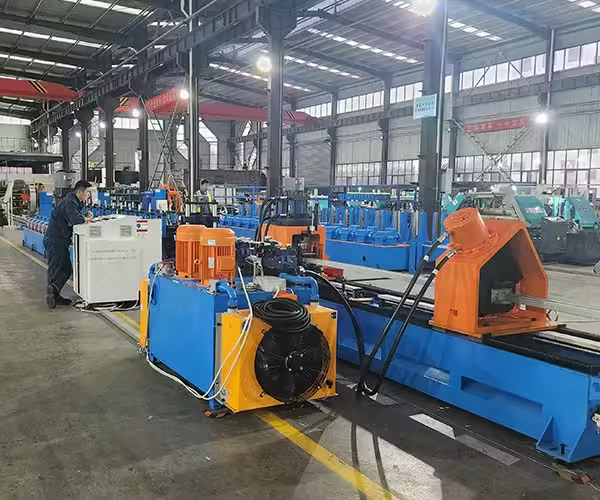
A solar support bracket forming machine line processes coiled metal into structural profiles used in photovoltaic mounting systems. Depending on the product, the line may complete decoiling, leveling, feeding, punching, roll forming, cutting, marking, unloading, turning, and stacking.
Manufacturers producing different solar mounting profiles can review the available solar photovoltaic bracket forming machines before selecting a line configuration.
Basic Production Line
A basic production line usually includes:
- Decoiler
- Coil-loading device
- Leveling and feeding unit
- Punching station
- Roll forming machine
- Cutting system
- Run-out table
- PLC control system
This configuration may be suitable for factories with a stable profile, moderate output, and manual finished-product handling.
Fully Automated Production Line
A fully automated line may also include:
- Coil-head alignment
- Automatic strip welding
- Material accumulator or looper
- Multiple punching stations
- Servo tracking cutter
- Product marking
- Automatic unloading
- Robotic material displacement
- Profile turning
- Automatic stacking
- Production-data recording
- Energy-consumption monitoring
- Remote diagnostics
The Jinbolida solar mounting production line integrates loading and storage, cold roll forming, servo tracking cutting, unloading, turning, and stacking functions.
Start the Layout with the Finished Bracket
The correct layout should begin with the product specification rather than the available machine model.
Before drawing the production line, define:
- Profile cross section
- Finished length
- Material grade
- Material thickness
- Coil width
- Maximum coil weight
- Hole dimensions
- Hole spacing
- Number of punched surfaces
- Required length tolerance
- Required hole-position tolerance
- Surface-protection requirements
- Product quantity per shift
- Number of profile specifications
- Expected changeover frequency
These factors affect almost every part of the solar support bracket forming machine line.
For example, a long C-channel with several holes on three sides may require a different feeding and punching arrangement from a short U-channel with a simple bottom-hole pattern.
Recommended Solar Support Bracket Forming Machine Sequence
The most common arrangement follows the direction of material flow.
1. Raw Material Storage
The coil-storage area should be located near the beginning of the line. It should provide enough room for incoming coils, material identification, temporary storage, and safe movement by crane or forklift.
The storage plan should account for:
- Coil outside diameter
- Coil inside diameter
- Maximum coil weight
- Number of material grades
- Number of coating types
- Daily coil consumption
- First-in, first-out management
- Quarantine space for unapproved material
A separate inspection area can be used to verify coil thickness, width, coating, surface condition, and material documentation before production.
2. Coil Loading and Decoiling
The decoiler supports and releases the coil into the production line. It may be manual, hydraulic, single-head, or double-head.
A double-head decoiler can reduce coil-change downtime because a replacement coil can be prepared while the previous coil is being processed. However, it requires more floor space and a more detailed material-handling plan.
Allow sufficient clearance for:
- Coil loading
- Mandrel expansion
- Support-arm movement
- Coil-car travel
- Coil replacement
- Maintenance
- Safety guarding
The crane or forklift route should not cross the normal operator walkway.
3. Coil Head Preparation and Strip Joining
High-output lines may include a coil-head preparation station and strip welder. These components connect the end of one coil with the beginning of the next coil.
Continuous strip joining can reduce machine stops, but the joint must be controlled so it does not damage downstream punching dies, rollers, or cutting tools.
When Is Strip Welding Useful?
Strip welding is most useful when:
- The line operates for long shifts.
- Coil changes occur frequently.
- Production interruption must be minimized.
- A material accumulator is included.
- The joint can be removed or managed safely.
For lower-volume production, manual coil replacement may be simpler and more economical.
4. Material Accumulator or Looper
A looper temporarily stores metal strip between the coil-feeding section and the forming section.
It allows the upstream area to stop for coil joining while the downstream equipment continues running from the stored strip.
The accumulator length should be based on:
- Normal line speed
- Time required to change or join coils
- Material thickness
- Strip width
- Available floor space
- Safe loop depth
A looper improves continuity but increases line length and requires appropriate guarding.
5. Leveling and Servo Feeding
The leveling unit removes coil curvature and prepares the strip for accurate punching and forming.
A servo feeder controls the material movement according to the programmed hole spacing, cutting length, and production recipe.
The leveling and feeding system should be selected according to:
- Material thickness
- Yield strength
- Coil width
- Required feeding accuracy
- Punching frequency
- Surface sensitivity
High-strength or thick material may require larger leveling rollers and greater drive capacity.
Where Should Punching Be Positioned?
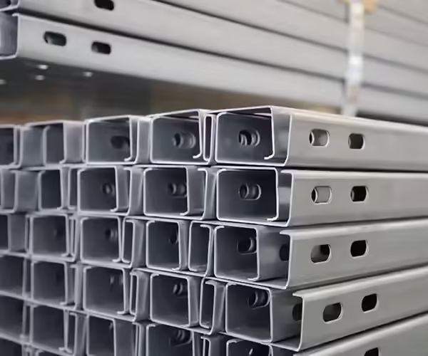
Punching may be installed before forming, during forming, or after forming. The correct location depends on the bracket geometry and the surfaces that require holes.
Pre-Punching
Pre-punching processes the flat strip before it enters the roll forming section.
Its advantages include:
- Easier die design
- Convenient access to several hole patterns
- Simple scrap removal
- Efficient processing of flat material
- Easier maintenance
However, the forming process may slightly change the final position or shape of some holes. The machine design must compensate for material movement and profile deformation.
Post-Punching
Post-punching processes the completed profile after forming.
It may provide a more direct relationship between the hole and the final profile geometry. However, the tooling must fit around the formed component, and punching several sides can require a more complex system.
Separate Punching Cell
A separate punching machine may be appropriate when the factory handles many hole patterns, low-volume customized orders, or existing formed profiles.
Jinbolida’s solar photovoltaic rack punching equipment includes multi-station configurations for processing holes on different sides of C-shaped steel.
For smaller connection components, the solar photovoltaic bracket connector punching machine combines punching, cutting, and forming. Its published configuration lists a cycle time of 3–5 seconds per component and positioning accuracy of ±0.5 mm.
| Punching Arrangement | Best Suited For | Main Advantage | Main Limitation |
|---|---|---|---|
| Pre-punching | Flat strip with repeatable hole patterns | Simple tooling and material flow | Forming may affect final hole position |
| Post-punching | Holes referenced to finished profile | Direct control from formed geometry | Tooling access can be difficult |
| Inline multi-station punching | High-volume bracket production | Continuous automated processing | Higher initial investment |
| Separate punching cell | Customized or low-volume orders | Flexible production scheduling | Additional material handling |
| Connector production machine | Short brackets and connectors | Punching, cutting, and forming in one cycle | Not intended for long support rails |
Roll Forming Section Layout
The roll forming section gradually shapes the strip through a sequence of roller stations.
The required machine length depends on:
- Profile complexity
- Material thickness
- Yield strength
- Number of bends
- Minimum bend radius
- Required production speed
- Number of forming stations
- Straightening requirements
Dedicated Profile Line
A dedicated line is designed for one main profile family. It normally offers simpler adjustment, stable quality, and efficient mass production.
Factories focused on C-shaped profiles can evaluate a solar photovoltaic bracket C-channel roll forming machine.
Flexible Profile Line
A flexible line may use adjustable rollers, interchangeable tooling, replaceable cassettes, or automatic dimensional adjustment.
Factories producing U-shaped supports can also compare a solar photovoltaic bracket U-channel forming machine.
The published C-channel and U-channel configurations both list production speeds of up to 45 m/min, ±1 mm precision, approximately 40 kW power, and customizable floor space of about 35 m × 5 m. These values should be treated as configuration references rather than guaranteed output for every profile.
Cutting and Length Control
The cutting system is normally located after the forming section, although pre-cut configurations are also possible.
Stop-to-Cut System
The line stops briefly while the profile is cut.
This configuration is relatively simple, but repeated stops can reduce output and increase the mechanical load during acceleration and deceleration.
Servo Tracking Cutter
A servo tracking cutter moves with the profile during cutting. The roll forming section can continue operating while the cutter follows the material.
This method can improve line continuity, but it requires accurate synchronization between the encoder, servo drive, cutter, and PLC.
The selected cutting system should match:
- Profile shape
- Material strength
- Line speed
- Cut length
- Length tolerance
- Cut surface requirement
- Burr limitation
Unloading, Turning, and Stacking Area
The end of the production line is often underestimated during layout planning.
Long solar support profiles require enough space for safe discharge and organized stacking. Manual collection can become a bottleneck even when the upstream equipment is operating efficiently.
Manual Run-Out Table
A manual table is suitable for lower output or shorter products. Operators collect, inspect, and stack profiles by hand.
Its advantages are low investment and simple operation. Its disadvantages include higher labor demand, inconsistent stacking, and a greater risk of surface damage.
Automatic Stacking System
An automated stacking system may include:
- Discharge conveyor
- Profile separation
- CNC displacement
- Automatic turning
- Counting
- Layer formation
- Bundle preparation
- Finished stack transfer
Automatic stacking is especially valuable for long profiles, high line speeds, and multiple-shift production.
Straight, U-Shaped, or Separated Layout?
The overall factory arrangement can follow several patterns.
| Layout Type | Advantages | Limitations | Recommended Application |
| Straight-line layout | Simple material flow and easy monitoring | Requires a long workshop | New factories with sufficient length |
| U-shaped layout | Shorter travel distance between start and finish | Requires controlled profile turning | Limited building length |
| L-shaped layout | Uses corner space efficiently | Material direction changes once | Irregular factory buildings |
| Separate production cells | Flexible scheduling and maintenance | More material transfers | High product variety |
| Parallel lines | High total output and shared services | Requires greater width | Large-volume manufacturers |
Straight-Line Layout
A straight-line arrangement is generally the easiest to understand and manage. The coil enters at one end and the finished bracket leaves at the other.
It provides clear material flow, but the workshop must be long enough for the decoiler, accumulator, punching system, roll former, cutter, stacker, and maintenance clearance.
U-Shaped Layout
A U-shaped layout reduces the distance between the material-entry and finished-product areas.
However, metal strip or long finished profiles cannot simply turn through a tight corner. The line must be divided at a logical transfer point, such as after cutting or between separate production cells.
Separated Production Cells
In a separated layout, punching, forming, and finishing operate as individual cells.
This approach can be useful when orders vary significantly, but it increases material handling, work-in-process inventory, scheduling complexity, and positioning requirements.
How Much Factory Space Is Required?
The machine footprint shown on a quotation is not the same as the required production area.
The layout should also include:
- Raw coil storage
- Coil loading
- Operator walkways
- Electrical cabinet access
- Hydraulic maintenance
- Punching die replacement
- Roller adjustment
- Cutting-tool maintenance
- Safety fencing
- Finished-product inspection
- Stacking
- Packaging
- Scrap collection
- Forklift routes
- Emergency exits
Jinbolida’s published full solar mounting production line configuration lists a customizable reference floor area of approximately 65 m × 11 m. Its configuration includes loading and storage, cold roll forming, servo tracking cutting, unloading, turning, and stacking. A smaller dedicated C-channel or U-channel line may use a reference footprint of approximately 35 m × 5 m.
Recommended Clearance Areas
As a planning principle, provide access around components that require frequent adjustment or maintenance.
Particular attention should be given to:
- Decoiler expansion mechanism
- Leveling rollers
- Punching dies
- Roller stations
- Drive system
- Hydraulic cutter
- Electrical cabinet
- Lubrication points
- Scrap discharge
- Stacking system
The final clearance should follow the equipment supplier’s drawings and applicable local safety regulations.
Utility Planning for the Production Line
A solar support bracket forming machine line may require electricity, compressed air, hydraulic oil, cooling, network access, lighting, and ventilation.
Electrical Supply
Confirm:
- Local voltage
- Frequency
- Phase
- Installed power
- Normal operating power
- Starting current
- Transformer capacity
- Cable route
- Earthing
- Backup power requirements
The full production line published by Jinbolida lists approximately 90 kW of equipment power, while the company’s dedicated C-channel and U-channel lines list approximately 40 kW. Actual requirements depend on the agreed configuration.
Compressed Air
Compressed air may be required for clamps, marking, material separation, stacking, and other pneumatic components.
The supplier should specify pressure, flow rate, air quality, and connection size.
Network and Data Connection
An intelligent production line may record output, energy consumption, alarms, recipes, downtime, and maintenance information.
Network planning should include:
- Ethernet connection
- Remote-service access
- Data security
- User permissions
- Local data storage
- Backup procedures
- Operation during network interruption
How to Calculate Real Production Capacity
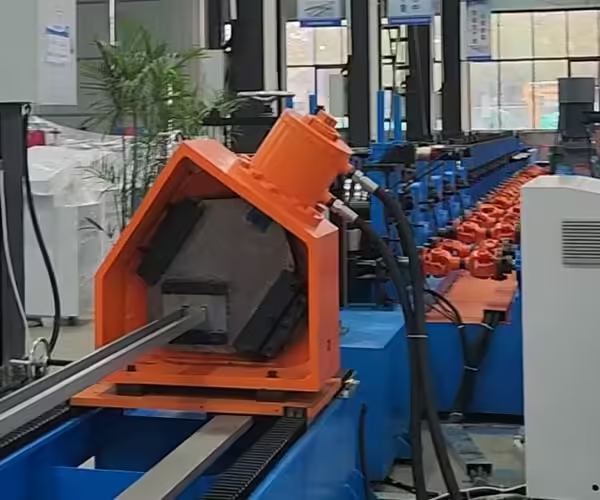
Do not calculate output using line speed alone.
The real cycle is affected by:
- Number of holes per product
- Punching stroke frequency
- Product length
- Cutting cycle
- Acceleration and deceleration
- Coil replacement
- Profile changeover
- Inspection
- Stacking
- Maintenance
- Operator efficiency
- Material availability
Example Capacity Logic
A line operating at 30 meters per minute does not necessarily produce 1,800 meters every hour.
The calculation must deduct:
- Coil-loading time
- Punching delays
- Cutting delays
- Tool adjustments
- Product collection
- Quality checks
- Planned breaks
- Minor stops
Ask the supplier to provide both:
- Maximum mechanical speed
- Guaranteed output under an agreed product specification
The guaranteed test should use the actual bracket length, material thickness, and hole pattern.
Compare Three Levels of Automation
| Automation Level | Typical Configuration | Labor Requirement | Suitable Factory |
| Basic | Decoiler, feeder, former, cutter, run-out table | Higher | Low-volume or startup production |
| Semi-automatic | Servo feeding, punching, forming, cutting, manual stacking | Medium | Stable medium-volume orders |
| Fully automatic | Coil joining, accumulation, punching, forming, tracking cut, robotic stacking | Lower | High-volume continuous production |
Basic Line
A basic solar support bracket forming machine has a lower initial investment and simpler maintenance. It may be appropriate when labor is available and production quantities are moderate.
Semi-Automatic Line
A semi-automatic line balances investment and efficiency. The key forming, punching, and cutting steps are controlled automatically, while loading and stacking remain partly manual.
Fully Automatic Line
A fully automatic line reduces repeated handling and can improve consistency. Its value is highest when the manufacturer has stable orders, multiple shifts, long profiles, and clear production-management procedures.
Automation should solve a real production problem rather than simply increase the number of components.
Material Standards and Product Requirements
The production line must be configured according to the material and project requirements defined by the buyer.
For galvanized steel sheet, ASTM A653/A653M-25a covers zinc-coated and zinc-iron alloy-coated steel sheet produced by the hot-dip process in coils and cut lengths. The standard includes multiple material designations and grades with different mechanical-property requirements.
For photovoltaic array projects, IEC 62548-1:2023+AMD1:2025 addresses PV array design requirements and includes revised mounting-structure requirements. Equipment buyers should still identify the specific national, structural, corrosion, and customer standards that apply to their finished brackets.
The machine supplier does not determine the project’s structural requirements. The buyer should provide the approved bracket drawing, material grade, coating, tolerance, and inspection requirements.
Safety and Maintenance Access
A fast line is not productive when maintenance is difficult or unsafe.
The layout should include:
- Emergency stops
- Safety fences
- Interlocked access doors
- Warning lights
- Accessible control stations
- Protected electrical cabinets
- Safe die-change areas
- Lockout points
- Clearly marked walkways
- Scrap-removal access
- Fire-safety access
- Emergency exits
Maintenance Planning
The supplier should identify:
- Daily inspection points
- Lubrication schedule
- Roller-cleaning procedure
- Punch and die replacement
- Cutting-blade replacement
- Hydraulic filter replacement
- Electrical inspection
- Recommended spare parts
- Required maintenance tools
Keep enough space to remove shafts, rollers, dies, motors, and cylinders without dismantling unrelated equipment.
Factory Acceptance and Site Acceptance
The line layout should be verified before shipping and after installation.
Factory Acceptance Test
The factory acceptance test should confirm:
- Material feeding
- Punching sequence
- Profile dimensions
- Hole position
- Cutting length
- Line speed
- Recipe selection
- Changeover
- Alarm functions
- Continuous operation
- Finished-product stacking
Use the buyer’s actual material whenever possible.
Site Acceptance Test
The site acceptance test should confirm:
- Foundation and anchoring
- Electrical supply
- Compressed air
- Hydraulic operation
- Machine alignment
- Safety systems
- Operator training
- Trial production
- Final product quality
- Documentation delivery
| Acceptance Item | FAT | SAT |
| Machine configuration | Verify | Reconfirm |
| Product dimensions | Test | Test again |
| Punching accuracy | Test | Test again |
| Utilities | Simulated or factory supply | Actual factory supply |
| Layout clearance | Review drawing | Verify on site |
| Operator training | Preliminary | Complete |
| Safety functions | Test | Final verification |
| Continuous production | Factory trial | Site production trial |
Information to Send for a Line Layout Proposal
To receive an accurate solar support bracket forming machine layout, provide:
Product Details
- Cross-sectional drawing
- Finished-product length
- Hole pattern
- Hole size
- Tolerance
- Sample photograph
- Application
Material Details
- Material grade
- Yield strength
- Thickness
- Coil width
- Coil weight
- Coating type
- Surface requirements
Production Details
- Pieces per hour
- Tons per month
- Number of shifts
- Product mix
- Changeover frequency
- Planned future products
Factory Details
- Workshop drawing
- Column positions
- Door dimensions
- Crane capacity
- Floor loading
- Voltage and frequency
- Compressed-air supply
- Raw material route
- Finished-product route
For additional supplier-selection questions, read the roll forming machine buying guide.
Conclusion
A successful solar support bracket forming machine project depends on more than selecting a roll former. The complete line must connect coil storage, loading, leveling, punching, forming, cutting, unloading, inspection, stacking, and material movement into one efficient workflow.
The layout should be based on actual product drawings, material properties, hole patterns, output targets, factory dimensions, and future production plans.
Before confirming the equipment, compare the proposed line sequence, floor-space requirement, bottleneck capacity, maintenance access, utilities, automation level, and acceptance criteria.
For a customized line-layout proposal, send your bracket drawings, raw material information, production target, and workshop dimensions to the Jinbolida engineering team.
Solar Support Bracket Forming Machine FAQ
How much space does a solar support bracket forming machine need?
A dedicated forming line may require less space than a complete automated production line. The final area depends on the decoiler, punching, accumulator, roll former, cutter, stacking method, product length, and maintenance clearance. Always request a complete layout rather than relying only on the machine footprint.
Should the punching machine be placed before the roll former?
Pre-punching is common because the strip is flat and easy to process. Post-punching may be more suitable when holes must reference the finished profile. The correct position depends on the product drawing and required tolerance.
Can one production line make both C- and U-channel brackets?
A flexible line can produce several profiles when it is designed with adjustable or interchangeable tooling. Buyers should confirm the dimension range, tooling included, changeover procedure, and changeover time.
Is an automatic stacker necessary?
An automatic stacker is most valuable for long products, high production speeds, and continuous multi-shift operation. A manual table may be sufficient for lower output or short profiles.
What is the biggest production-line bottleneck?
The bottleneck may be punching, cutting, coil replacement, profile changeover, or stacking. The slowest repeated process determines the actual line capacity, not the maximum speed of the roll former.
How do I calculate production output?
Calculate output using the real product length, hole pattern, punching cycle, cutting cycle, coil changes, downtime, and stacking time. Ask the supplier to demonstrate guaranteed output using an agreed product specification.
What drawings are needed before installation?
The buyer should receive the general arrangement drawing, foundation drawing, electrical connection plan, pneumatic and hydraulic requirements, machine anchor positions, safety layout, and material-flow plan.
How should I request a customized production line?
Send the product drawings, material specifications, output target, factory layout, utility information, automation requirements, and required delivery schedule. This allows the supplier to prepare a practical technical proposal.
If you enjoyed this article on Jinbolida’s smart manufacturing and digital factory expertise, follow us for more insights and updates:
- 📘 Facebook: Stay tuned for our latest smart production line projects → Facebook
- 📱 WhatsApp: Contact us anytime for custom production solutions → Chat Now
- ▶️ YouTube: Watch our automated line demos and real-world applications → YouTube
Let’s keep innovating and shaping the future of smart manufacturing — together!
 English
  Arabic
  Russian
  Spanish
  French