
Équipement de support photovoltaïque : formage, poinçonnage, découpe et empilement
/ Photovoltaic Support Equipment: Forming, Punching, Cutting and Stacking
Table des matières
Introduction
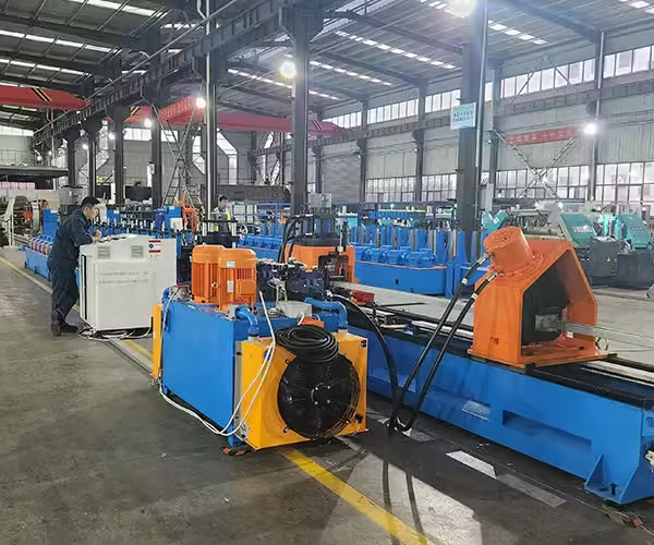
Photovoltaic support manufacturing involves more than converting steel coil into a C-channel or U-channel. A production system may need to prepare the coil, position material accurately, create holes and slots, form the required profile, cut it to length, transfer the finished component, turn it when necessary, and stack it for inspection or downstream handling.
For this reason, photovoltaic support equipment should be evaluated as an integrated manufacturing system rather than as a collection of independent machines. A high-speed roll former cannot deliver its expected factory output if punching repeatedly stops the material, cutting cannot keep pace, finished profiles accumulate at the discharge end, or operators spend excessive time moving products manually.
The U.S. Department of Energy identifies racking and tracking structures as manufactured products within the photovoltaic supply chain. Its overview of PV racking systems also explains that these structures support photovoltaic modules on roofs or in fields and that ground-mounted systems commonly use protected or galvanized steel.
For a manufacturer planning new équipement de fabrication de supports photovoltaïques, the practical objective is therefore not simply to purchase the fastest forming machine. It is to create a production flow in which forming, punching, cutting, material handling, and stacking are matched to the same finished product and production target.
Points clés à retenir
- Photovoltaic support production should be planned as one coordinated manufacturing process.
- Roll forming normally provides the core process for long C-channel, U-channel, and related support profiles.
- Punching may become the real production bottleneck when profiles contain dense or multi-face hole patterns.
- Cutting method affects both finished length control and practical line output.
- Automatic unloading and stacking can become increasingly valuable as line speed and profile length increase.
- Maximum meters per minute should not be treated as finished factory capacity.
- Equipment selection should begin with drawings, materials, hole patterns, product mix, batch size, and target output.
What Is Included in Photovoltaic Support Equipment?
Photovoltaic support equipment covers the machinery used to transform raw metal into finished structural components for solar mounting systems. The exact equipment depends on the type of support products a factory intends to manufacture.
For long profiles, the process commonly begins with coiled strip. The coil is loaded and decoiled before the material passes through feeding, punching, roll forming, cutting, and finished-product handling stages.
More automated production systems can add material storage, coil-head joining, servo feeding, multi-station punching, synchronized cutting, turning, automatic unloading, stacking, production-data collection, and other functions.
Short connector components can require a different process. Instead of continuous long-profile roll forming, they may be produced through punching, cutting, and forming cycles using dedicated equipment.
A useful way to understand photovoltaic support equipment is therefore to divide it by manufacturing function.
| Section Équipement | Fonction principale | Pourquoi c'est important |
|---|---|---|
| Manipulation de bobines | Load and supply raw material | Maintains stable material feeding |
| Nivellement et alimentation | Guide and position strip | Supports punching and forming accuracy |
| Perforation | Produce holes, slots and connection features | Determines assembly interfaces |
| Rouleau formant | Create C, U or custom cross-sections | Produces structural profile geometry |
| Coupe | Control finished length | Completes individual profiles |
| Déchargement | Remove product from line | Prevents downstream accumulation |
| Turning/transfer | Reposition finished profiles | Supports automated handling |
| Empilage | Organize finished products | Reduces repetitive manual handling |
| PLC/control | Coordinate machine operations | Connects production stages |
| Auxiliary equipment | Support material and tooling flow | Improves overall line efficiency |
The most important consideration is how these sections interact.
A well-designed line does not simply contain all of them. Their capacities and control logic need to be matched.
Start With the Finished Photovoltaic Support Profile
Machine selection should begin with the component drawing.
Before choosing a forming line, determine the profile cross-section, finished length, steel grade, material thickness, strip width, hole geometry, hole spacing, punched surfaces, cut shape, and expected production quantity.
These details influence nearly every equipment section.
A simple U-channel with a few repeated holes may require a relatively straightforward production configuration. A lipped C-channel containing several slot patterns on multiple surfaces can require more complex feeding and punching.
A customized mounting rail may add reinforcing ribs, return edges, or unusual connection features that change the forming sequence again.
This is why the existing machine de formage de supports solaires photovoltaïques category should be viewed as a family of equipment rather than one universal machine.
C-channel, U-channel, and customized profiles should each be evaluated according to their actual drawings.
Coil Handling Is the Beginning of Production Efficiency
Production problems can begin before the material reaches the roll former.
Steel coil must be loaded, centered, and supplied to the line in a controlled manner. If coil handling depends heavily on repeated manual adjustment, the upstream section can create unnecessary stops even when downstream equipment is capable of continuous operation.
A basic production system may use a decoiler that supplies strip directly to feeding equipment.
A more integrated line can add coil-loading devices, automatic head alignment, strip joining, or a material accumulator. These functions are particularly useful when manufacturers need to reduce interruptions between coils or coordinate upstream and downstream operations more closely.
L'actuel de Jinbolida Ligne de production de supports photovoltaïques integrates material loading and storage with cold-bending forming, servo-tracking cutting, unloading, turning, and stacking.
This kind of integration illustrates an important principle: automation begins with material flow, not only with the roll forming machine.
If the roll former repeatedly waits for material preparation, increasing forming speed alone will not improve daily output.
Why a Material Accumulator Can Matter
An accumulator or looper provides temporary strip storage between production stages.
Its purpose is to help separate the timing of upstream material preparation from the downstream forming process. For example, if a coil-head operation requires a short interruption, stored strip can help downstream equipment continue operating for part of that period.
Whether an accumulator is necessary depends on the production strategy.
A moderate-output line producing relatively small batches may not need the same material-storage configuration as a high-volume system intended for long continuous runs.
The decision should therefore be based on expected operating rhythm.
Equipment should be added because it removes a known bottleneck or supports a specific production objective, not simply because it appears in a fully automated line configuration.
Feeding Connects Punching With Forming
Once the strip enters the production process, feeding becomes critical.
The feeding system must control material movement so that holes, slots, cutting lengths, and other programmed features occur at the intended positions.
This is particularly important when a photovoltaic support profile contains repetitive hole patterns.
A small positioning inconsistency can be repeated across an entire production batch if the feeding and punching sequence is not properly coordinated.
Servo-controlled feeding can be useful for profiles requiring programmed pitch lengths or several hole locations. However, accurate servo movement alone does not guarantee a correct finished bracket.
The strip must also remain properly guided, the punch tooling must be correctly aligned, and subsequent roll forming must preserve the required relationship between punched features and the finished profile.
This is why inspection needs to focus on the finished component rather than only on the feeding system.
Roll Forming Is the Core of Long-Profile Manufacturing
For C-channel, U-channel, solar rails, strut-type profiles, and many other long open sections, roll forming normally provides the central manufacturing operation.
Metal strip passes through a sequence of roller stations. Each station introduces part of the required deformation until the finished cross-section is achieved.
The process is continuous, which makes it suitable for repeated production of long structural members.
However, one forming machine cannot automatically produce every photovoltaic profile.
The roller design depends on width, depth, bend angles, return lips, ribs, material thickness, mechanical properties, and other geometric features.
A C-channel with return lips can require a different forming progression from a basic U-channel. A custom rail containing reinforcing features may require another tooling strategy.
Manufacturers evaluating specific profile families can compare Jinbolida’s C-channel photovoltaic bracket roll forming machine et U-channel photovoltaic bracket forming machine as examples of equipment configured around different cross-sections.
More Forming Stations Do Not Automatically Mean a Better Machine
Station count is sometimes used as a simple equipment comparison, but the number alone provides limited information.
The correct number of roll forming stations depends on how the material needs to progress from flat strip to finished section.
A relatively simple open profile may require fewer forming stages. A deeper, lipped, asymmetric, or heavily reinforced section may require a more gradual forming sequence.
Adding stations without an engineering reason does not automatically improve product quality.
Likewise, reducing the number of stations simply to shorten the machine can lead to more aggressive deformation between passes.
The more useful question is how the forming sequence has been developed for the specific profile.
For custom projects, buyers should ask the machine supplier to evaluate the finished cross-section and explain whether any bends or features require particular forming attention.
Punching Is Often the Hidden Bottleneck
Many photovoltaic support profiles require holes and slots for assembly.
These features can be simple or extremely demanding from a production perspective.
A support rail containing two repeated web holes may allow relatively efficient processing. Another profile of the same length may contain round holes, elongated slots, notches, and side holes at multiple locations.
The second product may require much more punching time even though its roll forming section is almost identical.
For this reason, the practical capacity of photovoltaic support equipment frequently depends on the punching cycle.
The dedicated équipement de poinçonnage de supports photovoltaïques solaires range includes several punching configurations for different processing requirements.
The correct number of punching stations should be determined from the hole drawing rather than from a preference for a particular machine.
Poinçonnage à station unique ou multi-stations

Simple products may be processed effectively with a relatively straightforward punching arrangement.
As hole complexity increases, several operations may need to occur at different positions or on different surfaces.
Multi-station equipment can divide these operations across dedicated tooling positions.
Par exemple, celui de Jinbolida Poinçonneuse à neuf stations is designed around multi-side processing of C-shaped steel and multiple hole types within its specified working range.
That does not mean every solar support factory needs nine stations.
The lesson is that punching equipment should scale with product complexity.
If the finished support requires only one repeated hole type, excessive punching infrastructure provides little practical value. If a profile contains several hole groups across multiple surfaces, too simple a punching configuration can create a production bottleneck.
The drawing should determine the solution.
Pre-Punching vs Post-Punching Changes the Line Design
Punching location also changes the relationship among equipment sections.
Pre-punching creates holes while the strip is flat or before most forming operations occur. Tool access is generally easier because the material has not yet become a three-dimensional profile.
Post-punching processes the finished or near-finished section. This can be useful where hole position must reference final profile geometry more directly.
Each method has manufacturing tradeoffs.
Pre-punching may simplify dies and allow several positions across the strip to be reached easily, but subsequent forming must be considered when holes lie near bends.
Post-punching avoids some of that subsequent deformation but requires tooling capable of supporting and accessing the finished cross-section.
Le détaillé photovoltaic bracket roll forming machine pre-punching vs post-punching guide explains how these strategies affect tooling, accuracy, and line configuration.
For a complete photovoltaic support equipment plan, punching location should be decided before the final machine layout is frozen.
How Punching and Forming Should Be Balanced
Suppose the roll former can process material faster than the punch system.
The complete production line will still operate according to the slower punching requirement.
Increasing roller speed does not remove this restriction.
The same principle works in reverse. Installing an extremely fast punching system provides limited benefit if the profile cannot be formed or cut at a comparable rate.
The objective is balanced capacity.
Manufacturers should calculate the cycle for the actual product and identify which process becomes limiting.
For each representative profile, record:
- longueur finie;
- number of holes;
- number of punching strokes;
- number of punched surfaces;
- cycle de poinçonnage ;
- vitesse de formage;
- cutting time;
- unloading requirement.
This produces a more useful picture of the production system than comparing equipment specifications independently.
Cutting Is a Production Process, Not Just the Last Step
After forming, the profile needs to be separated at the required finished length.
The cutting method influences both product quality and line operation.
A stop-to-cut configuration pauses material movement during the cutting cycle. This can be practical for many products, particularly where required output does not justify a more complicated synchronized system.
A servo-tracking or flying cutting arrangement can reduce interruption to continuous production, although the mechanical and control requirements are more sophisticated.
Jinbolida Ligne de production de supports photovoltaïques currently integrates servo-tracking cutting into the wider line configuration together with forming and downstream handling.
The correct cutting method depends on profile geometry, finished length, required output, and cutting requirements.
Manufacturers should therefore calculate cutting frequency based on actual product length.
A line producing short supports will complete many more cutting cycles over the same processed length than a line producing long rails.
Cutting Tooling Must Match the Profile
Finished-profile cutting requires proper support.
A simple open U-channel and a deep lipped C-profile do not necessarily use the same cutting die design.
The tool needs to separate the profile while limiting unwanted deformation around the cut end.
This becomes particularly important for profiles that contain complex flanges, lips, ribs, or coated surfaces.
If one machine will manufacture several substantially different cross-sections, buyers should ask whether the cutting tooling is shared, adjustable, or replaced during changeover.
This question is sometimes overlooked when buyers focus primarily on roll forming flexibility.
A machine may be able to adjust the roller section for several dimensions while still requiring different cutting tools.
Unloading Becomes More Important as Output Increases
Finished products need to leave the cutting area quickly enough for the next production cycle to continue.
For low-volume production, operators may be able to collect and move profiles manually.
As line speed, profile length, or product weight increases, manual unloading can become increasingly difficult to coordinate with the upstream machine.
The result may be unnecessary stops.
If a line repeatedly pauses because operators cannot clear finished material from the discharge area, the actual production bottleneck is no longer forming or punching. It is material handling.
This is why downstream equipment deserves the same attention as the processing machines themselves.
A properly designed unloading system transfers finished profiles away from the cutter and creates space for subsequent pieces without unnecessary interference with the main production cycle.
When Automatic Turning Is Useful
Some finished support profiles need to be repositioned before stacking.
A turning mechanism can rotate or orient the product according to the required stacking arrangement.
This becomes useful when the natural exit orientation from the forming line is not suitable for stable stacking or when profiles need to nest in a particular way.
As with every automation feature, it should be evaluated from the product.
A simple lightweight profile that operators can handle easily may not justify the same turning system as a long heavy support manufactured continuously at high volume.
The question should be:
Does automatic turning remove a repetitive handling constraint or improve downstream flow?
If the answer is yes, it can become part of the production solution rather than an optional feature added without clear purpose.
Automatic Stacking Can Protect Line Capacity
Stacking is easy to underestimate because it occurs after the profile has already been manufactured.
But production is not complete when the part leaves the cutter.
Finished supports still need to be organized for inspection, bundling, storage, or transfer.
Manual stacking can become increasingly labor-intensive as line output rises.
Long profiles can require several workers to manage safely and consistently. Irregular stacking can also create unnecessary product movement later.
An automated stacking system can coordinate finished-profile placement with the rest of the line.
Le ligne de production de supports photovoltaïques currently presented by Jinbolida integrates precision unloading, material displacement, turning, and stacking into the downstream production sequence.
This is a useful example of why finished-product handling should be considered during initial line design rather than added only after the factory discovers that manual handling limits output.
Is an Automatic Stacker Always Necessary?
Non.
Automation level should reflect production conditions.
A factory producing moderate quantities of relatively short or lightweight profiles may operate efficiently with manual collection or a simple run-out table.
A high-output factory producing long supports continuously can face a completely different handling requirement.
Automatic stacking becomes more attractive when:
- line output is high;
- profiles are long;
- parts are difficult to handle manually;
- labor availability is limited;
- production runs continuously for long periods;
- consistent bundle organization is important;
- manual unloading is already causing machine stops.
The right automation decision is therefore based on bottleneck removal.
Not every manual process needs to be automated, but a manual process that repeatedly stops the entire line deserves close attention.
Auxiliary Equipment Connects the Main Machines
Some of the largest productivity improvements occur outside the primary forming and punching machines.
Coil carts, material accumulators, conveyors, loading systems, transfer equipment, turning devices, stacking systems, and other support machinery can reduce unnecessary manual movement.
Jinbolida groups these supporting systems under équipement auxiliaire de machine de formage.
The value of auxiliary equipment depends on how it fits into the complete process.
Adding automation at one point without considering the next stage can simply move the bottleneck.
For example, automated unloading provides limited benefit if products then accumulate at a manual inspection point that cannot keep pace.
The entire material path should therefore be evaluated from coil storage to finished-product storage.
How to Find the Real Production Bottleneck
Before purchasing additional equipment, manufacturers should identify which process is limiting actual production.
A bottleneck can appear in many places:
- coil loading;
- feeding;
- punching;
- forming;
- cutting;
- unloading;
- stacking;
- changement de profil ;
- tooling setup;
- inspection;
- material movement.
The line’s maximum output is constrained by the slowest necessary operation.
Suppose forming can support a higher speed but punching requires repeated stops. Adding a faster roll former may not increase finished output.
If punching and forming operate efficiently but workers stop the line every few minutes to remove products, unloading deserves attention.
If the line runs well during production but spends a large part of every shift changing tooling, changeover may be the more important productivity issue.
The correct improvement depends on measurement.
Maximum Line Speed Is Not Practical Capacity
A common purchasing mistake is treating maximum forming speed as factory capacity.
The line may be rated in meters per minute, but factories often need to know pieces per hour, tons per shift, or monthly output.
Those values depend on the finished product.
A long profile containing few holes may allow relatively continuous operation. A short component with dense punching can require far more interruptions.
Practical output also includes time lost to coil replacement, changeover, inspection, maintenance, and normal production stops.
The detailed methodology in Comment calculer la capacité de la ligne de production de supports solaires can be used to convert machine-level speed into a more realistic factory-output model.
For equipment comparison, suppliers should ideally calculate output using the same representative drawing.
This provides a far better comparison than placing two maximum speed figures side by side.
How to Match Equipment Capacity Across the Line
Each equipment section should be evaluated against the process immediately before and after it.
If the feeding system supports the required punching cycle, check whether the punching section can match forming.
If forming can maintain the target rate, verify that cutting can operate without excessive interruption.
If cutting meets the requirement, check whether unloading and stacking can clear finished products fast enough.
A simplified line-balance review might look like this:
| Processus | Capacity Question | Possible Bottleneck Signal |
| Alimentation | Can material reach every programmed position on time? | Punch waits for feed |
| Perforation | Can all required holes be completed within the target cycle? | Forming waits for punching |
| Formation | Can profile geometry remain stable at target speed? | Quality drops as speed increases |
| Coupe | Can every finished length be separated on time? | Line repeatedly stops at cutter |
| Déchargement | Can products leave the cutting area continuously? | Les profils finis s'accumulent |
| Empilage | Can parts be organized at line output rate? | Operators stop production to clear material |
This kind of analysis turns automation from a feature list into a production-engineering decision.
Dedicated Equipment vs Integrated Production Line
Factories generally have two broad approaches.
The first is to operate several independent machines. Punching may occur in one area, roll forming in another, and finished parts can be moved manually between operations.
The second is to integrate several processes into one coordinated production line.
Independent equipment can offer flexibility, especially for low-volume custom products or factories that already own suitable machinery.
Integration can reduce intermediate handling and coordinate the process more closely when production volume and product stability justify it.
The correct choice depends on product mix.
A factory producing one high-volume photovoltaic support profile may benefit significantly from an integrated line.
A contract manufacturer producing many small batches could value independent equipment differently.
Neither configuration should be selected simply because it appears more automated.
The decision should follow real production requirements.
When an Integrated Photovoltaic Bracket Production Line Makes Sense

Integration becomes attractive when several conditions occur together.
The product has stable demand, the manufacturing steps are repetitive, production volume is significant, and the factory wants to reduce intermediate handling between separate processes.
In this environment, connecting feeding, forming, cutting, unloading, and stacking can create a more continuous production flow.
Jinbolida Ligne de production de supports photovoltaïques is currently configured around integrated loading and storage, C/U-shaped cold-bending forming, servo-tracking cutting, precision unloading, turning, and stacking.
For manufacturers planning the physical arrangement of these processes, the Disposition de la ligne de machine de formage de support solaire guide goes further into factory space, material flow, maintenance access, utilities, punching, forming, cutting, and downstream handling.
Equipment selection and factory layout should be considered together because an efficient machine can still perform poorly when surrounding material flow is badly organized.
When Separate Punching Equipment Is More Practical
Not every punching requirement should be placed inline.
A factory may produce several profiles with substantially different hole patterns. Integrating every possible punch configuration into one forming line can make tooling complicated and changeovers inefficient.
Separate punching can be useful when:
- products require very different hole layouts;
- several profile families share one forming line;
- connector components are processed independently;
- punching capacity needs to operate separately from forming;
- small custom batches occur frequently.
The dedicated équipement de poinçonnage de supports photovoltaïques solaires range can therefore act as a separate part of the equipment matrix rather than only as an inline accessory.
The decision should be based on material flow and product mix.
Separating processes introduces additional handling, but it can also increase flexibility.
Connector Components Need Their Own Production Logic
A photovoltaic support system includes more than long structural rails.
Short connectors, joining pieces, and related components may require punching, cutting, and forming in compact cycles.
These parts should not automatically be routed through the long-profile roll forming line.
Le Machine de poinçonnage de connecteurs de supports photovoltaïques solaires represents a different equipment strategy focused on short photovoltaic connection components.
Separating connector production can allow the main roll forming line to continue manufacturing long structural profiles without repeated interruptions for completely different products.
This also makes capacity planning more accurate.
Long profiles can be evaluated in meters per minute and pieces per shift, while short connector equipment may be evaluated primarily according to cycle time or parts per hour.
Product Changeover Must Be Included in Equipment Planning
Photovoltaic support factories often produce more than one specification.
A machine may switch between C-channel sizes, U-channel dimensions, different hole patterns, or several customer-specific products.
Every change can consume production time.
Depending on the equipment, changeover may involve roller adjustment, guide adjustment, punching-die replacement, cutting-tool replacement, PLC recipe selection, and first-article inspection.
A technically flexible machine can therefore become operationally inefficient if changeovers are frequent and difficult.
Buyers should ask exactly how a planned product change is performed.
Which settings change automatically? Which adjustments are manual? What tooling is replaced? How is the new position referenced? What dimensions need to be checked before full production restarts?
This information is essential when batch sizes are small.
C-Channel and U-Channel Equipment Should Be Evaluated Separately
C-channel and U-channel profiles belong to related photovoltaic support families, but their tooling requirements can differ.
L'existant Machine de formage de rouleaux de support de montage solaire C vs profils U guide explains how profile geometry affects machine selection.
From an equipment-integration perspective, the important issue is whether the planned products can share enough of the production line to make changeover practical.
Closely related sizes may be suitable for an adjustable system.
Substantially different profiles can require interchangeable rollers or independent lines.
A manufacturer with one dominant C-channel product and a smaller U-channel range may reach a different equipment decision from a manufacturer whose annual output is evenly distributed across both families.
Product volume should therefore be considered together with technical feasibility.
How Automation Changes Labor Requirements
Automation does not simply replace individual manual actions. Its greater value can be the coordination of several production stages.
If feeding, punching, forming, cutting, unloading, and stacking are linked through the same production sequence, operators spend less time repeatedly moving semi-finished material between machines.
However, automated systems still require operators for setup, monitoring, inspection, tooling change, maintenance, and production management.
The correct staffing model depends on line configuration and factory procedures.
Equipment selection should therefore avoid unrealistic assumptions that “automatic” means “unattended.”
The more useful question is which repetitive operations consume labor today and whether automation can remove those specific constraints without creating unnecessary complexity.
PLC Control Should Coordinate the Process
The control system connects several machine operations.
Depending on the equipment configuration, programmed information may include finished length, punching position, batch quantity, cutting commands, and product recipes.
This becomes particularly useful when a factory repeatedly produces established specifications.
Operators can select a validated recipe instead of entering every value manually each time.
However, digital control does not replace mechanical setup.
If roller positions, punching dies, guides, or cutting tools need to change, the physical machine still needs to be configured correctly.
Reliable production therefore combines control-system repeatability with standardized mechanical changeover and first-piece inspection.
Production Data Can Support Bottleneck Analysis
More advanced production systems may record production counts, equipment conditions, energy consumption, alarms, or other operating information.
The main benefit is visibility.
If a factory knows how much scheduled time is lost to punching stops, coil changes, tool setup, or downstream handling, future improvement becomes more targeted.
Without production data, operators may assume that the forming machine needs to be faster when the real loss occurs elsewhere.
Digital production information is therefore most valuable when it supports a specific operational decision.
Collecting data for its own sake provides limited value.
The factory should define which indicators are useful for production planning, maintenance, quality, and capacity improvement.
Quality Control Should Be Built Into the Production Flow
Inspection should not be treated only as an activity performed after a complete batch is finished.
Critical dimensions should be checked at appropriate points during production.
For photovoltaic support profiles, inspection can include cross-sectional dimensions, flange geometry, straightness, twist, hole spacing, slot position, cut length, end condition, and visible surface quality.
Which dimensions deserve the greatest attention depends on the approved component drawing.
Features that determine assembly or interface with other racking components are normally more important than dimensions that have little effect on function.
After a product changeover, the first finished component should be checked before the line returns to full batch production.
This prevents an incorrect setup from producing a large quantity of nonconforming material.
Coated Material Requires Care Throughout the Line
The DOE notes that ground-mounted PV racking commonly uses steel with protective coatings or galvanization. The manufacturing line therefore needs to process the specified surface without unnecessary damage.
Surface handling should be considered at several stages.
Rollers and guides need to remain clean. Punching scrap should not contaminate the material path. Cutting and discharge equipment should avoid unnecessary scratching. Finished profiles should not rub excessively during transfer and stacking.
Surface damage may not alter the profile dimensions, but it can reduce finished-product quality and create additional inspection or rework.
A complete photovoltaic support equipment plan should therefore include material handling and maintenance procedures alongside machine specifications.
Factory Layout Can Limit Otherwise Good Equipment
Production equipment needs room to operate.
The line layout should include more than the physical dimensions of the machines.
Space may be required for coil storage, loading equipment, tooling storage, maintenance, electrical cabinets, hydraulic systems, operator access, quality inspection, forklifts, cranes, finished-product staging, and future expansion.
Long support profiles also require sufficient space after cutting.
A machine installed too close to a wall may become difficult to maintain. A discharge area that crosses a forklift route can create unnecessary handling problems.
For this reason, the support solaire formant la disposition de la ligne de machine should be reviewed before equipment is installed rather than after individual machines have already been positioned.
Material should move through the factory logically from raw coil to finished support.
How to Decide Which Sections Should Be Automated
Automation priorities should follow the actual bottlenecks.
A useful order of analysis is:
First, identify which operations frequently stop production.
Second, calculate how much scheduled production time those stops consume.
Third, determine whether the cause is machine capacity, manual handling, setup, inspection, or another process.
Fourth, evaluate whether automation genuinely removes the constraint.
For example, an automatic stacker can provide significant value when manual collection repeatedly stops a fast production line.
The same stacker may provide little return on a low-volume line that spends most of its time changing products.
Likewise, adding more punching stations is useful only if punching complexity is limiting output.
Automation should therefore be targeted rather than decorative.
Building a Basic vs Automated PV Support Production Line
Manufacturers can compare production configurations according to their actual operating model.
| Configuration | Ligne de base | More Automated Line |
| Chargement de bobine | Manual/semi-assisted | Integrated loading |
| Coil continuity | Regular coil change | Head joining and strip storage possible |
| Alimentation | Standard feeding | Servo coordinated feeding |
| Perforation | Basic inline or separate | Multi-station/integrated punching |
| Formation | Rouleau formant | Roll forming with coordinated controls |
| Coupe | Stop-to-cut possible | Servo tracking or synchronized cutting |
| Déchargement | Manual/run-out table | Déchargement automatique |
| Tournant | Manuel | Automatic turning where required |
| Empilage | Manuel | Empilage automatique |
| Données de production | Basic machine information | Integrated production monitoring |
| Le mieux adapté à | Moderate output, simple products | High-volume repetitive production |
The automated line is not automatically better.
The correct configuration depends on volume, product variety, labor model, floor space, capital strategy, and future expansion plans.
What Information Should Be Included in an RFQ?
A useful RFQ gives the equipment supplier enough information to design the complete process.
| Article RFQ | Informations à fournir | Pourquoi c'est important |
| Dessins de profil | Complete finished cross-sections | Détermine l'outillage de roulis |
| Dessins de trous | Hole type, position and spacing | Détermine le poinçonnage |
| Matériel | Qualité et revêtement | Affecte le comportement de formation |
| Épaisseur | Gamme pour chaque profil | Affects machine load |
| Coil specifications | Width and maximum coil weight | Determines feeding and decoiling |
| Longueur du produit | Min/max/common lengths | Determines cutting cycle |
| Mélange de produits | Percentage by profile | Supports line strategy |
| Taille du lot | Typical run quantity | Détermine l'impact du basculement |
| Sortie requise | Pieces or tons per shift/month | Soutient la planification des capacités |
| Dimensions critiques | Drawing requirements | Defines quality control |
| Espace usine | Available dimensions | Determines layout |
| Utilitaires | Electrical and plant requirements | Supports installation |
| Cible d'automatisation | Required material-handling functions | Defines auxiliary equipment |
| Future products | Planned profile expansion | Supports scalability |
Providing several representative drawings is particularly useful.
The supplier should see the most common product, the most complex punching pattern, the thickest material, and the profiles most likely to require frequent changeovers.
How to Compare Two Photovoltaic Support Equipment Proposals
Equipment comparisons should use the same product assumptions.
Send both suppliers identical profile drawings, materials, hole patterns, lengths, and production targets.
Then compare the proposed process.
How is material loaded? Where is punching performed? How many stations are used? How is the profile formed? What cutting method is proposed? How does the finished part leave the line? Is stacking manual or automatic? What is changed when the product changes? Which operation limits practical output?
This provides a much clearer comparison than reviewing maximum speed, motor power, or machine length individually.
Ask suppliers to state the production assumptions behind their output claims.
A capacity figure without a product drawing, hole pattern, finished length, and operating condition provides limited planning value.
Factory Acceptance Testing Should Cover the Complete Line
A factory acceptance test should verify the integrated production process.
Where practical, testing should use representative material and an agreed photovoltaic support drawing.
The line should demonstrate feeding, punching where applicable, roll forming, cutting, unloading, control, and other included automation.
Finished products should then be inspected against agreed requirements.
If automatic turning and stacking are part of the purchased line, those systems should also operate during the test.
The objective is not merely to prove that each individual machine can run.
It is to demonstrate that the equipment works together as the production system that was specified.
For multi-profile equipment, the acceptance plan should also define whether one or more product changeovers need to be demonstrated.
Common Mistakes When Planning Photovoltaic Support Equipment
One common mistake is purchasing the roll forming machine before finalizing the hole pattern. Punching can substantially change the required equipment and production cycle.
Another is comparing machines by maximum forming speed while ignoring cutting, punching, unloading, and stacking.
A third mistake is attempting to process every support and connector component on one line. Long rails and short connection parts may require different manufacturing methods.
Factories can also underestimate material handling. A fast production line can still experience frequent stops when operators cannot remove or stack finished profiles quickly enough.
Another common issue is excessive flexibility. A machine may technically produce many specifications, but frequent long changeovers can reduce practical factory output.
Finally, automation is sometimes selected before the factory has identified its actual bottlenecks.
The more reliable sequence is product definition first, process design second, automation level third.
How to Configure the Right Photovoltaic Support Equipment System
Begin with the product portfolio.
Group long C-channel, U-channel, rails, customized profiles, and connector components according to their manufacturing process.
Determine which products represent the greatest production volume.
Next, define the punching complexity for each profile. Decide whether punching is best integrated before forming, after forming, or handled separately.
Then select the forming strategy.
High-volume stable profiles may justify dedicated tooling. Related profile sizes may benefit from adjustment. Significantly different cross-sections may require interchangeable rollers or separate lines.
Calculate output from the complete production cycle.
Do not stop at meters per minute.
Finally, evaluate coil handling, unloading, turning, stacking, tooling storage, inspection, maintenance access, and factory expansion.
This method produces a photovoltaic support equipment system designed around manufacturing requirements rather than around a list of machine features.
Conclusion
Photovoltaic support equipment works best when forming, punching, cutting, unloading, and stacking are treated as parts of one manufacturing system.
Roll forming creates the structural profile, but it does not determine factory performance by itself. Punching can control the production cycle when hole patterns are complex. Cutting frequency changes with product length. Manual unloading can restrict high-speed lines, while changeover can reduce effective output in factories producing many specifications.
The correct level of automation therefore depends on the actual product and production model.
Manufacturers should begin with complete drawings, material specifications, hole layouts, batch sizes, monthly production targets, and expected product mix. These inputs provide the basis for deciding which operations should be integrated, which should remain separate, and where automated handling can create measurable value.
For projects requiring a more integrated configuration, Jinbolida’s Ligne de production de supports photovoltaïques combines material loading, cold-bending forming, cutting, unloading, turning, and stacking, while the broader range of photovoltaic support manufacturing equipment includes dedicated forming, punching, connector-processing, and auxiliary equipment for different production requirements.
FAQ
What equipment is needed to manufacture photovoltaic supports?
A typical production system can include a decoiler, feeding equipment, punching system, roll forming machine, cutting equipment, unloading system, and PLC control. Higher-automation lines may also use strip storage, automatic turning, stacking, and production-data functions. The exact equipment depends on the support profile and hole pattern.
Is punching normally integrated with photovoltaic support roll forming?
It can be integrated or operated separately. Inline punching can provide an efficient continuous workflow for stable high-volume products, while separate punching may offer greater flexibility for multiple profiles or complex hole patterns. The choice should be based on the actual finished drawings and production mix.
Is automatic stacking necessary for a PV bracket production line?
Not for every factory. Manual stacking can remain practical for moderate output and manageable products. Automatic stacking becomes more valuable when profiles are long, line output is high, labor-intensive handling repeatedly interrupts production, or organized continuous downstream flow is required.
What is usually the bottleneck in photovoltaic support manufacturing?
There is no universal bottleneck. Depending on the product, capacity may be limited by punching, cutting, profile changeover, coil replacement, unloading, stacking, inspection, or material handling. The correct approach is to measure the full production cycle before deciding which machine or automation section needs improvement.
How should I choose photovoltaic support equipment for a new factory?
Start with finished product drawings, material specifications, hole patterns, product lengths, expected batch quantities, product mix, and required output. Use this information to determine forming, punching, cutting, and handling requirements, then design the automation level and factory layout around the complete production process.
 French
  English
  Arabic
  Russian
  Spanish